Member postings for Nicholas Farr
Here is a list of all the postings Nicholas Farr has made in our forums. Click on a thread name to jump to the thread.
| Thread: Motor wont start |
| 02/06/2011 09:24:14 |
Hi Alan, the fact that if you spin the motor in the wrong direction and it stops and starts in the correct direction, does sound as if it is kind of working. This maybe mean the starting field is weak, or in the wrong place electrically, this fact could suggest that a capacitor may be needed, because it would shift the phase angle in the starting field towards to ideal position. By the age of the motor, a capacitor may not have been mounted on the motor itself originally.
When you measure the DC resistance of the windings, a split-phase one will probably only have a difference of 2 to 5 ohms. If the difference is widely different say 10 to 30 ohms, it could indicate a capacitor is needed.
Regards Nick. |
| 01/06/2011 03:00:55 |
Hi Alan, you will probably find that the start winding is the one with the higher DC resistance. The best way to check which is which, is with a low voltage AC supply, say 12V @ 0.5 amps. Apply the voltage across each winding in turn with an ammeter in the circuit and a volt meter across the windings, the start winding should take the most current and have a lower voltage across the windings.
It's all to do with reactance and inductance stuff in AC circuits. The running winding has a higher inductance than the start winding and will draw less current than the start winding. In contrast the start winding will have a lower inductance and will draw a high current during start up, which has to be switched off when up to speed, or it will overheat.
AC resistance isn't as straight forward as DC resistance.
Regards Nick. |
| 31/05/2011 22:28:38 |
Hi, capacitor-start motors need a switch to cut the capacitor and start winding out when the motor has reach full speed. This is also normally done with a centrifugal switch on the rotor.
A split-phase motor or a capacitor motor will run without the start winding in circuit, if is is spun during start up, it will run in which ever direction it is spun in. Once these motors are running, the start winding or any capacitor play no further part.
Below is a scan of single-phase capacitor motors.
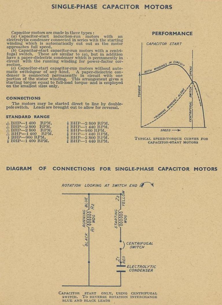 Hope this helps. Regards Nick.
Edited By Nicholas Farr on 31/05/2011 22:54:07 |
| 30/05/2011 22:46:23 |
Posted by Alan Worland on 30/05/2011 21:04:22:
How would I know? Hi Alan, there may be clues to one being attached to the outside by a bracket hole or two, and/or an extra space for the wires for it, to enter into the connection box. There would be no harm in trying a suitable one. In the WPS no 16 Electric Motors by Jim Cox, 50 Mfd or more per horsepower at 240V 50 Hz are needed for start capacitors.
Regards Nick |
| Thread: The Cambridge Turning Trials |
| 30/05/2011 22:11:24 |
Hi Andrew, very interesting, and a very good presentation of your results, very easy to follow the individual trials.
Regards Nick |
| Thread: This months MEW are 3 CNC features two too many |
| 30/05/2011 22:03:42 |
Posted by David Clark 1 on 30/05/2011 21:06:08:
Hi Andrew
On the grounds it does not look like a prototype engine, round head screws, overall finish was poor and brass for the conecting rod pin.
regards David
Hi, well I think it looks quite an elegant engine in its own way, even without being painted.
I thought this was a simple steam series, and the author did say it was not be considered a true scale model.
I'm sure that most people who don't like the shape of the screws can put in alternatives, and choose thier own materials for pins ect.
Regards Nick. |
| Thread: which mill and lathe ... advice please if poss |
| 30/05/2011 13:00:21 |
Hi, I bought a secondhand Boxford 4 1/2" BUD from a place in Glasgow, which is about 380 miles from me. As it weighed around 200/250 Kg. it went on my trailer with no problem. They are certainly worth their money IMO, and as they were a popular model for schools, a beginner shouldn't have much problem learning on one.
On Tony's web site, www.lathes.co.uk he points out how they can be broken down into manageable lumps, to fit into a car as small as a MK1 Golf, for reasonable easy transport.
It's always best to shop around a bit for a second hand lathe, if that is the root you decide to take, but if you are unsure as to what the condition for the price is, it is always good to ask someone you can trust to help you.
One advantage of buying a second hand lathe to learn on I suppose is, if you do any damage to it while learning, it doesn't hurt the pocket as much as a brand new £1 K + machine might, of which you might be a bit timid to use until you gain a bit of confidence.
Regards Nick. |
| Thread: Sparky Circuit Help wanted |
| 28/05/2011 09:56:37 |
Hi Richard, just to show Les's description, the scan below should make it clearer.
Regards Nick. |
| 26/05/2011 00:33:30 |
Hi Richard, I agree with Les, they should all be OK, but the lead outs for BC212 and BC337 are different from the 2N3702/4, below is a diagram of them.
L20 is the BC212/337 and L21 is the 2N3702/4
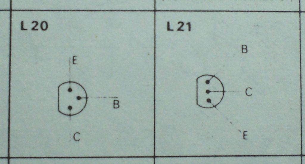 The BD242 and TIP32 have the same lead outs, as in this diagram below. 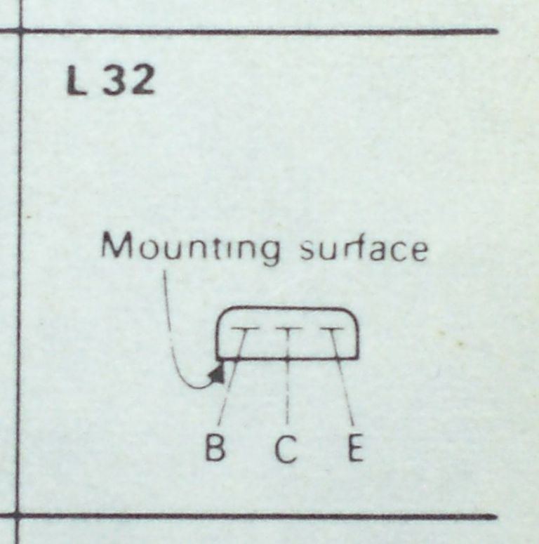 Hope these help. Regards Nick. |
| Thread: Sieg Super X3 advice needed! |
| 24/05/2011 10:32:54 |
Hi, I've been stripping down cleaning/repairing and rebuilding machines, a lot of them more complex than your average hobby machine, all my working life. It started when I was first able to use a screwdriver, because if my toys could come apart, then they did. My mother once asked why I used to take them apart almost five minutes after I had them, and apparently I said "to see how they work"
Disassembling machinary is not everyones cup of tea, and if you don't have the ability or confidence to take a brand new machine apart and rebuild it, it can be a very expensive learning curve.
Some people can use machines to make and build things that they have a control over, but don't always know, or need to know how the internals of the machine works. I would prep the machine myself, if I ever bought one.
Regards Nick. Edited By Nicholas Farr on 24/05/2011 10:36:17 |
| Thread: Adams wheels |
| 21/05/2011 08:43:21 |
Hi, I've had another study of the photos, and I'm thinking that on the back wheels the spokes may be a shade too long, causing the hub to be slightly rotated clockwise in respect to the rim. Moving the spokes round one hole on the rim may make it look the other way. A photo looking square on to them would show it better, as the front wheels look OK radially.
The front wheels look as if they are a heavier duty than the back wheels with the same number of spokes in them. Having said that, they do look a tidy job.
Regards Nick. |
| Thread: That's better! |
| 21/05/2011 00:03:40 |
Hi, any flat surface is fatal, because I'll just pop that on there for now and then that bit and then ... oh! that'll just fit there till I want it. Next thing you know in a few days is I'm hunting for a particular tool or a lump of metal and get frustrated looking for it.
Anyway I think if you see a bench thats always tidy, you tend to think maybe not a lot of work happens on it, because to much time is spent clearing up. I do put tools away sometimes, but then it seems to be worse, as I can't always think where they are, it's esayer to remember when you last used them.
Regards Nick. |
| Thread: Myford ML7 travelling steady 'fingers' size |
| 18/05/2011 08:12:13 |
Hi Martin, two other threads with concerns about condensation were, "Workshop Heating" and "Using Butane"
Regards Nick. |
| Thread: Correcting pilot error |
| 15/05/2011 18:42:56 |
Hi David, in which case I'd go for Micheal's idea with the Loctite and pin, and then heed Jason's advice about the dot punch.
Regards Nick. |
| Thread: MEW 177 digital Issue |
| 15/05/2011 16:09:38 |
Hi Paul, I don't have the seperate sub, but when I klick on the link in my account for the Digital Issues it goes to ME and/or MEW digital links and clicking on MEW one brings it up.
Regards Nick. |
| Thread: This months MEW are 3 CNC features two too many |
| 15/05/2011 15:40:33 |
Hi, having now read Chris Trice's post, it reminds me of an electronics mag I used to buy many years ago, and then the PC revolution took off and the mag had about 90% of its contents every month about add on computer boards, and programming codes, it became boring and therefore stopped buying it. Not sure if is even still going now.
Regards Nick. Edited By Nicholas Farr on 15/05/2011 15:41:26 |
| 15/05/2011 15:22:49 |
Hi, I kinda agree with every-one's posts. I don't have any CNC machines, and am not likely to, any time soon, that's not because I'm against it, as I can see its value. However, along with the three CNC article there are two Myford articles as well (alright I know one Myford article is also one of the CNC articles) and apart from an old "M" type Myford that I bought off a work mate a while ago because he had a cash flow problem, I don't have much interest in Myford articles either. So you might think I'm a bit hard done by with this issue of MEW. But at least the information is there should I ever have any need of it in the future, and one issue with what may or may not be too many CNC articles is not going to make me consider cancelling my subscription, but like mjg says, if it becomes full of it or even becomes a to frequently thing of more than one article per issue, then yes I most likely would not renew my subscription next time.
I can only see one page with any amount of G Code, and as it's an introduction article about CNC milling I guess it can be justified, I have not read it through yet, but may well do in the next week.
I think it is only fair that all interests in this field of engineering should be covered, not always full of only the one's we like ourselves.
Regards Nick. Edited By Nicholas Farr on 15/05/2011 15:28:26 |
| Thread: Building a hand drill press |
| 14/05/2011 22:51:33 |
Hi Steve, I'm not sure that you have totally understood the action of the feed mechanism, as there is only the one thread on the drilling spindle that is engaged into the fly wheel at all times. When the fly wheel is rotating, it is in the same direction as the drilling spindle. The drilling spindle is only fed down when the fly wheel is not rotating, or is rotating at a slower speed than the drilling spindle. The slower the fly wheel turns, the greater the feed is on the drilling spindle. The fly wheel will continue to spin briefly after cranking stops, due to the inertia built up in it while in rotation.
Did you read the explanations below each picture in my album, the other thread that you may be mistaken to contribute to the feed mechanism, is probably the small stop screw in the top of the spindle with the left hand thread. This only stops the spindle from dropping out of the machine, and serves no other purpose.
The feed rate is controlled by the pressure screw by slowing the fly wheel down with respect to the drilling spindle. I did not put the lock nut and bottom bearing on the fly wheel, as I've only put it together loosely for the photo, as I will be repainting it before finally reassembling completely, with new pins to hold the gears in place on there own spindles.
Regards Nick. |
| 13/05/2011 22:40:56 |
Hi Steve, apologies if I've confused you, but the hex rod is screwed into the top of the drilling spindle in place of the original stop screw, and travels down/up with it. This hex rod passes through a clutch plate, which is a sliding fit, the plate being driven by the hex rod. The cluch plate is nipped between the bottom plate which sits on top of the fly wheel boss with a distance piece to clear all protrusions and the top of the drilling spindle when in the fully up position, and the pressure plate which is what the spring is pressing onto.
Below is a photo of the hex rod and clutch plate, and a simple sketch of the assembly. The spring and adjusting screws/rods are omitted from the sketch. A hex rod was not specified in the original article, but was left to ones own choice, based on the author's own construction due to the number of different styles of this type of drill.
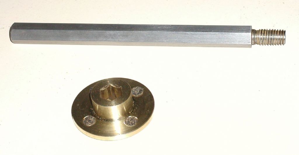 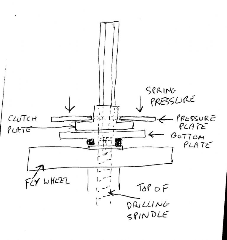 Hope this is not to difficult to understand, as its only a quick rough and ready sketch. Regards Nick. |
| 13/05/2011 00:09:27 |
Hi Steve, I have uploaded photos of the drill head that I dismantled and cleaned yesterday. They are in the album called 2 Speed Auto Hand Drill. I have included a photo of E.J. Slzlumper's design which I made for a drill of the same principle some years ago.
The drill spindle on this type of auto feed machine, is driven down onto the work, by the thread at the top of the drilling spindle, against a threaded portion inside the fly wheel shaft. The fly wheel remains stationary when there is no feedback pressure on the drilling spindle. Once the twist drill engages onto the work piece, feedback pressure increases the friction between the threaded portion of the drilling spindle and the thread inside the fly wheel shaft. This will start to rotate the fly wheel and most of the downward force on the drilling spindle is cancelled out. The amount of cancelling out can be reduced by increasing the pressure on the ball that acts on the fly wheel shaft by screwing in the pressure screw, thus increasing the amount of cut on the twist drill. If you stop the drilling action before completing the hole being drilled, the fly wheel will continue to rotate for a few revs, (depending on the amount of pressure on the adjusting screw) and lift the drilling spindle off the work piece.
One downside to this principle, is that the amount of friction on the threaded portion of the drilling spindle is not quite great enough to start the fly wheel rotating, and thus reducing the downward force on the drilling spindle when using the smaller twist drills and the result is that they break, this is what prompted E.J. Szlumper to come up with his design after reading letters in ME about others having this problem with this type of machine.
Regards Nick. |
Magazine Locator
Want the latest issue of Model Engineer or Model Engineers' Workshop? Use our magazine locator links to find your nearest stockist!
Sign up to our Newsletter
Sign up to our newsletter and get a free digital issue.
You can unsubscribe at anytime. View our privacy policy at www.mortons.co.uk/privacy
Latest Forum Posts
- hemingway ball turner
04/07/2025 14:40:26 - *Oct 2023: FORUM MIGRATION TIMELINE*
05/10/2023 07:57:11 - Making ER11 collet chuck
05/10/2023 07:56:24 - What did you do today? 2023
05/10/2023 07:25:01 - Orrery
05/10/2023 06:00:41 - Wera hand-tools
05/10/2023 05:47:07 - New member
05/10/2023 04:40:11 - Problems with external pot on at1 vfd
05/10/2023 00:06:32 - Drain plug
04/10/2023 23:36:17 - digi phase converter for 10 machines.....
04/10/2023 23:13:48 - More Latest Posts...
- View All Topics
Support Our Partners


Shopping Partners
Subscription Offer

Latest "For Sale" Ads
- Reeves** - Rebuilt Royal Scot by Martin Evans
by John Broughton
£300.00 - BRITANNIA 5" GAUGE James Perrier
by Jon Seabright 1
£2,500.00 - Drill Grinder - for restoration
by Nigel Graham 2
£0.00 - WARCO WM18 MILLING MACHINE
by Alex Chudley
£1,200.00 - MYFORD SUPER 7 LATHE
by Alex Chudley
£2,000.00 - More "For Sale" Ads...
Latest "Wanted" Ads
- D1-3 backplate
by Michael Horley
Price Not Specified - fixed steady for a Colchester bantam mark1 800
by George Jervis
Price Not Specified - lbsc pansy
by JACK SIDEBOTHAM
Price Not Specified - Pratt Burnerd multifit chuck key.
by Tim Riome
Price Not Specified - BANDSAW BLADE WELDER
by HUGH
Price Not Specified - More "Wanted" Ads...
Get In Touch!
Do you want to contact the Model Engineer and Model Engineers' Workshop team?
You can contact us by phone, mail or email about the magazines including becoming a contributor, submitting reader's letters or making queries about articles. You can also get in touch about this website, advertising or other general issues.
Click THIS LINK for full contact details.
For subscription issues please see THIS LINK.
Digital Back Issues


Donate

 Register
 Log-in
Model Engineer Magazine
- Percival Marshall
- M.E. History
- LittleLEC
- M.E. Clock

ME Workshop
- An Adcock
- & Shipley
- Horizontal
- Mill

Subscribe Now
- Great savings
- Delivered to your door

Pre-order your copy!
- Delivered to your doorstep!
- Free UK delivery!