Member postings for John Coates
Here is a list of all the postings John Coates has made in our forums. Click on a thread name to jump to the thread.
| Thread: Removing needle roller bearings ? |
| 04/05/2011 06:32:00 |
Why not turn a 16mm long cylinder to fit in the inside diameter of the bearing then bore this with a taper and slit with three or four slits. Then turn a taper to match but slightly larger so when tightened into the cylinder it forces the cylinder to grip the ID of the bearing as the slits allow expansion.
Bore through to take a threaded rod (8 or 10mm). Weld a nut on the end of the rod as this will stop it all falling into the tube. Thread the cylinder and taper onto the rod and insert into the bearing. Next put a washer and nut onto the rod and tighten so it forces the cylinder to expand and grip the bearing. Grip the tube in a vice (protect outer surface of tube). Now make a U frame with a flat plate drilled in the centre with the diameter of the threaded rod. Support this against the face of the vice. Now put put a washer and nut on and tighten so that it pulls the bearing up.
Basically what I'm describing is a bearing puller !
john |
| Thread: Which Mini Mill to Purchase?? |
| 03/05/2011 20:53:46 |
I've got an old Chester Champion. The round column is a pain as I lose register whenever I raise or lower the head when having to change tools so go for a something other than this - square or with a rack. The four speeds seemed limiting in respect of choosing an appropriate speed for the size of cutter and material so I have recently converted it to 3 phase (inverter and new motor plus making an adapter collar for the drive cone).
It is robust and has coped with my cack handed learning as a newbie. I'm getting more adventurous now though!
I spent £375 on the mill second hand and must have spent over that again on tooling and I still don't have all I need. At least that gives me an excuse to go to the ME show at Harrogate.
Chester have been very good with email communications when I needed help and they have a good support forum.
Hope this helps.
John |
| Thread: Indexable toolholder grinding/milling/shaping |
| 27/04/2011 15:55:42 |
| Sorry. Stupid Blackberry doesn't show when I've successfully posted. Hence the multiple postings |
| 27/04/2011 15:50:36 |
| I had to mill a couple of mm off my tool holders and open the bore of the case hardened QCTP from 7/16ths to 1/2" so have no fear of modding John |
| 27/04/2011 15:39:58 |
| Martin I've milled a couple of mill off my tool holders to fit my QCTP which was case hardened and had to be bored out from 7/16ths to 1/2" So let adaptation and modification be your guide! John (On holiday sitting in the sun by the side of a loch in the Great Glen) |
| Thread: Machining lugs |
| 18/04/2011 21:03:12 |
Ahh  I thought the lug was on the end of the bar, not in the middle D'oh! |
| 18/04/2011 19:56:15 |
Make a square jig to sit the round bar in, clamp to milling table then turn through 90 degrees to mill each face of the lug and then face the end? |
| Thread: Technical and engineering drawing. |
| 18/04/2011 12:31:57 |
How would this fit alongside the Workshop Practice book no.13 on Workshop Drawing out of interest? (as I bought that to help me)
I did TD from a building perspective (no pun intended) for my HNC so it was architectural detailing, plans and elevations and isometric perspectives. Having gotten into this hobby it gave me a bit of a headstart but didn't help with the shading used to show cut aways etc. So that is an area/topic I think would be well worth covering
John |
| Thread: Shed for a workshop - any advice? |
| 22/03/2011 12:42:18 |
Thanks everyone for some excellent advice
Peter - I have seen the WP series book and will buy it, maybe at Harrogate if it's on offer otherwise it's cheap on ebay
I'm going to price up the materials for making one. It will sit on a base of 5" thick concrete on 5" compacted hardcore. My mate is a builder so he can do this and I'll use his account to buy all the materials. The shed will sit on 100x100mm bearers at 300 centres. Marine ply on top then moisture barrier then 100x100 floor joists lining up with the bearers beneath. In between the joists will be insulation (board or roll) then the floor will be thick plywood. Walls will be 75x50 struts at 600 centres with ply in and out, insulation in between, shiplap cladding with moisture barrier behind as weather proofing to exterior. Roof will be felt, bubble wrap, another layer of ply, moisture barrier, insulation, ceiling.
This pricing exercise will help inform the make or buy" decision. Haven't decided on windows yet. Might just have none !
Ian - it's feet. Only the engineering stuff will be in there. Motorbikes and house related stuff will stay in the garage.
Thanks again |
| 21/03/2011 21:37:22 |
Graham
Thanks for the advice. Problem in lining the garage with insulation is that it has shelves, racking, power cables and electrical kit fixed to the walls. And it is ram jack full of stuff. It would take two days to empty it with no where to put the stuff whilst it was insulated out. So I had discounted that option as just too much damned hard work.
John |
| 21/03/2011 21:10:23 |
Me again
As the memory of a winter in the garage and frozen fingers fumbling cold steel, thoughts are turning to having a nice workshop dedicated to the machine and tooling. Having measured the back garden I reckon an 8 x 16 shed will fit snugly in a corner.
The ones on ebay range between £700 and £3,000 but I'm not convinced they will be up to the job. The frames seem a bit light to take the weight of half a ton of lathe (the mill is practically aneroxic in comparison at 165 kgs) and I wonder whether they will have sufficient depth to let me add insulation board and a panel on top.
Doodling at work I came up with a sketch with the base being 100 or 75mm square bearers with marine ply flooring on top, then insulation sat between the same sized joists, then another layer of plywood on top as the finished floor. Walls and ceiling would be 50mm or 75mm and insulated as well with plywood covering. This I felt would be strong enough or is it overkill ?
Will either build it myself, get one built by a local company or see if something like this can be bought ready built, depending on price and practicality
So has anyone any advice as to what specification I should be aiming for?
Thanks again as usual
 John |
| Thread: A woodworking question |
| 21/03/2011 13:19:04 |
Definitely R&D then
The thought of one of my first major bits of design and manufacture being a base for the fixed steady which will then help with a new base for the tailstock (broke locking lug, want it further forward into a gap in the saddle, want indexing on the tailstock) gives me goosebumps. The starting bit of metal will be big (well defintiely for the tailstock base) as the bars are 1.5" dia and 4.5" apart requiring quite a bit of accurate (for a newbie like me) metal removal
Oh well I guess jumping in at the deep end as opposed to mincing about on the shoreline dipping toes in the water should make a metal basher out of me ! |
| 21/03/2011 12:10:44 |
Nicholas and Jason - a chap at work is going to lend me his set of router bits and I have my endmills so to the miling machine it is ! Hopefully Weds night when I get back from a business trip, if not then after that.
The timber is the planed stuff bought from Wickes for fence rails (left over from a fence repair). The idea is that the wooden jobbie gets me up and running to sort the motorbike out (OK if we're being pedantic about it then yes, it is a bodge) then at a later date I can design and build in metal a more permanent solution.
 here's to bodging! here's to bodging! |
| 20/03/2011 22:18:48 |
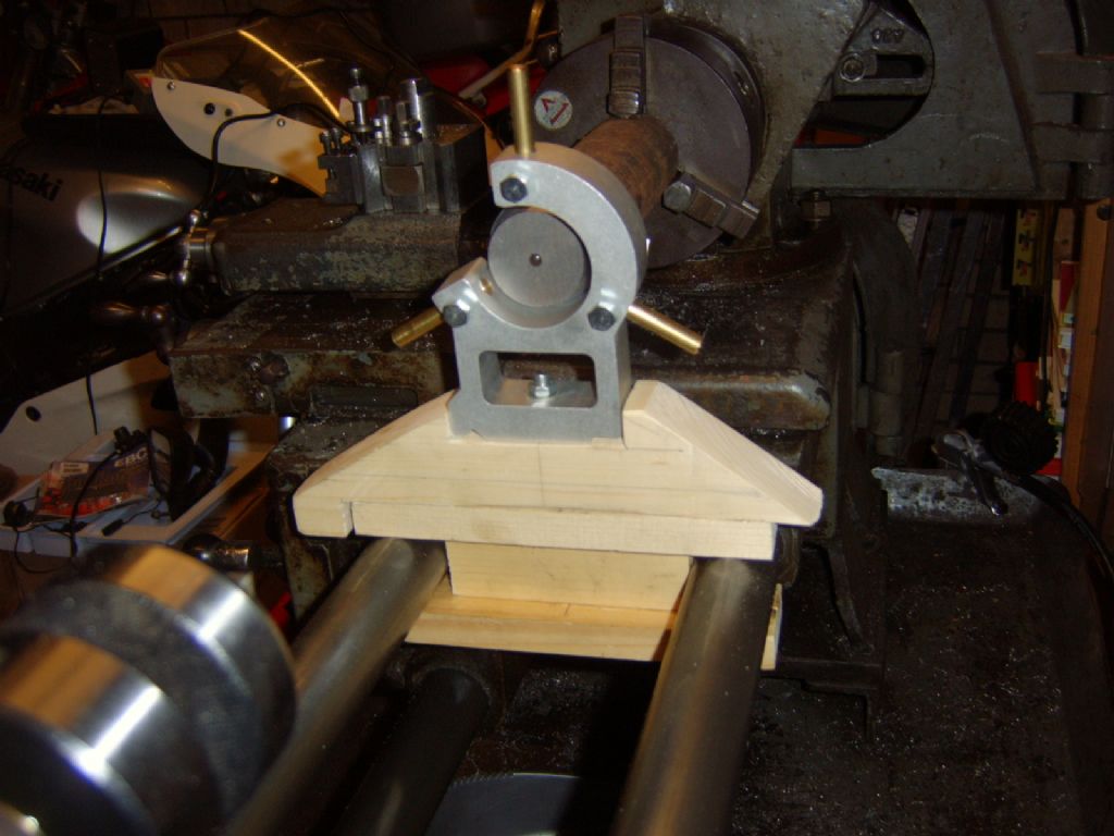
It only needs to come down about 4-5mm to put that bar in the centre of the steady
The reason for my need can just be seen in the background - my motorcycle (silver tank, white race fairing). I sold the race wheels that were on it and can't find the spacers for the OEM wheels. Hence I'm making them.
Imagine a top hat with a bore. The brim of the hat is 48mm dia with the main part 40mm dia with the bore for the spindle at 25mm dia. What you can see in the photo is the end of the 40mm dia which now has to be bored out. Once done the spacer will be parted off behind the "brim"
|
| 20/03/2011 22:11:05 |
Hi Terry
Here it is:
 |
| 20/03/2011 21:58:22 |
Thanks chaps
Les - yes that's it. Imagine two bars 4.5" apart. A vertical piece of wood sits between them with a flat piece above and below. This clamps the steady to the bar bed. I am then making up the wood between the top of this and the bottom of the steady. This is the piece,lets call it the upright, that I need to reduce and maintain squareness. I don't have a router, just saws, chisels, a jigsaw and pillar drill for woodwork.
Jason - I did think of using the mill but thought it would rip the wood to bits. Its not a hardwood so would splinter and disintegrate
I think I'm going to try putting the upright in my vice (with protective ally angle iron over the jaws) with a little bit projecting above and then square this up. Using an electric planer or sander (borrowed) I will take off a little at a time until the necessary amount is removed. The wood had two end stops which precluded this but one of those gave way tonight (see I knew there would be a cock up somewhere along the way, there always is) so I now have a flat surface to work on. My main aim is to keep it all square and sawing left a few wavy surfaces that I am now trying to true up and keep square |
| 20/03/2011 17:57:59 |
I needed to make a fixed steady for my lathe. I had already bought one and today made up a wooden structure to fix it to the round bars of the lathe bed. Now everything has gone well with no major catastrophes (which is a first for me). Luckily I did what I planned and made it slightly oversize so I can fine tune it
Now I need some advice as to how to take off millimetres off the oversize wood to get it to be accurate and at centre height. So far I have used a coping saw, a jigsaw, a rasp and sandpaper. Will these tools be sufficient to accurately reduce a section about 18mm by 80mm. My main problem is maintaining a flat parallel surface so the steady remains true.
My initial thoughts were to use sandpaper and a sanding block but this tends to produce a rounded hillock type result due to my technique.
What should I be doing and how should I be doing it?
Thanks
John |
| Thread: The boat that Guy built |
| 19/03/2011 22:58:50 |
My wife's father was a welder most of his life and a rather good one, albeit an alcoholic which is what ultimately claimed him. He didn't leave much but one thing I do have is a book from goodness knows when called "The Practical Man's Book of Things to Make and Do". Inside are six fold out plans for many "things" including a folding card table, an under bed wardrobe and a summer house. A veritable treasure trove for the inquiring mind with time on its hands.
|
| Thread: VFD Drives |
| 17/03/2011 21:16:33 |
Must admit I have had no problems after converting my lathe and mill to VFD with an inverter per machine. All I did was buy some shielded cable and each one has this connected between motor and inverter with the shielding fixed to the ground point of the inverter. Have a DAB radio within three feet of the lathe motor and about 6" of the shielded cable to that motor and it has no interference whatsoever.
Have you used shielded cable in your setup?
regards
John |
| Thread: Milling a square lump of steel that isn't square |
| 10/03/2011 21:58:13 |
UPDATE
All worked out well in the end. I used a piece of wood against the rough face and the good face against the fixed jaw. Got the majority of material removed by milling with an endmill and am now finishing off with a fly cutter taking lighter cuts for a better finish
Thanks to all and I enjoyed the segway into apprenticeships and former trials and tribulations
|
Magazine Locator
Want the latest issue of Model Engineer or Model Engineers' Workshop? Use our magazine locator links to find your nearest stockist!
Sign up to our Newsletter
Sign up to our newsletter and get a free digital issue.
You can unsubscribe at anytime. View our privacy policy at www.mortons.co.uk/privacy
Latest Forum Posts
- hemingway ball turner
04/07/2025 14:40:26 - *Oct 2023: FORUM MIGRATION TIMELINE*
05/10/2023 07:57:11 - Making ER11 collet chuck
05/10/2023 07:56:24 - What did you do today? 2023
05/10/2023 07:25:01 - Orrery
05/10/2023 06:00:41 - Wera hand-tools
05/10/2023 05:47:07 - New member
05/10/2023 04:40:11 - Problems with external pot on at1 vfd
05/10/2023 00:06:32 - Drain plug
04/10/2023 23:36:17 - digi phase converter for 10 machines.....
04/10/2023 23:13:48 - More Latest Posts...
- View All Topics
Support Our Partners


Shopping Partners
Subscription Offer

Latest "For Sale" Ads
- Reeves** - Rebuilt Royal Scot by Martin Evans
by John Broughton
£300.00 - BRITANNIA 5" GAUGE James Perrier
by Jon Seabright 1
£2,500.00 - Drill Grinder - for restoration
by Nigel Graham 2
£0.00 - WARCO WM18 MILLING MACHINE
by Alex Chudley
£1,200.00 - MYFORD SUPER 7 LATHE
by Alex Chudley
£2,000.00 - More "For Sale" Ads...
Latest "Wanted" Ads
- D1-3 backplate
by Michael Horley
Price Not Specified - fixed steady for a Colchester bantam mark1 800
by George Jervis
Price Not Specified - lbsc pansy
by JACK SIDEBOTHAM
Price Not Specified - Pratt Burnerd multifit chuck key.
by Tim Riome
Price Not Specified - BANDSAW BLADE WELDER
by HUGH
Price Not Specified - More "Wanted" Ads...
Get In Touch!
Do you want to contact the Model Engineer and Model Engineers' Workshop team?
You can contact us by phone, mail or email about the magazines including becoming a contributor, submitting reader's letters or making queries about articles. You can also get in touch about this website, advertising or other general issues.
Click THIS LINK for full contact details.
For subscription issues please see THIS LINK.
Digital Back Issues


Donate

 Register
 Log-in
Model Engineer Magazine
- Percival Marshall
- M.E. History
- LittleLEC
- M.E. Clock

ME Workshop
- An Adcock
- & Shipley
- Horizontal
- Mill

Subscribe Now
- Great savings
- Delivered to your door

Pre-order your copy!
- Delivered to your doorstep!
- Free UK delivery!