Member postings for Les Jones 1
Here is a list of all the postings Les Jones 1 has made in our forums. Click on a thread name to jump to the thread.
| Thread: Richmond Radial Drill wiring? |
| 15/04/2011 10:05:37 |
Hi Ronnie, I can tell you what I think some of the items in the control box are. Starting at the top left. Below the panel with the the screw terminals and fuses I think there is a transformer from 440 V to 110 volts for supplying the coils on the contactors. (Contactor is just another name for heavy duty relays.) The transformer does look a little on the large size just to supply the coils on the contactors. To the right of this there is a vertical metal panel which looks like it may have some components fixed to it. If this is the case they could be a delay circuit for star/delta starting. The item at the top and just to the right of this panel is a relay. The two square things on the top right look like selenium rectifiers. (If they are they will consist of many metal plates with spacers between them mounted on a threaded rod.) The other four items look like contactors. As there a four I suspect the motor may be a two speed type. (Only two contactors would be required for the star/delta starter.) I would not suggest connecting the supply to the terminals A, B, D without getting someone to trace out the wiring diagram. The two fuses are probably for the transformer so the non transformer end of these should go directly to two of the incoming phases You will probably find this end of the fuses go to two of the three sets of contacts on one or more of the contactors. If there are more than three sets of contacts used on the contactors then some will be connected to the control wiring and hence eliminated from the three phase wiring. I suspect you will need someone with electrical knowledge to help you. I live about 200 miles from you so I cannot offer to help. I must complement you on providing enough information (Including you location.) to enable people to try to help you. Les. |
| Thread: Users comments on these machines |
| 10/04/2011 09:16:31 |
Hi Graham, Most home made power feeds I have seen on other forums for milling machines seem to use either windscreen wiper motors or the motor / gearbox from cordless drills. Another suggestion I have seen is to use a stepper motor with a suitable controller. As windscreen motors use a worm gear you would need to put some form of clutch between the motor and the lead screw to enable manual feed to be used. If you decide on an X3 then when you wash out the head assembly in paraffin do not be as liberal as I was. The paraffin dissolves the adhesive on the label on the front as you can see in the picture of my mill. Les. |
| 08/04/2011 21:58:56 |
Hi Graham, Here is my home made power feed. It is no real help as the motor is one I was given many years ago from some unknown photocopier. 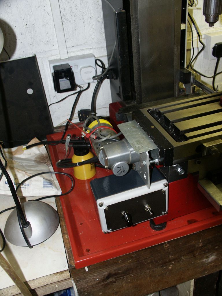 The motor was ideal for this application as it had an optical encoder on the end to provide closed loop speed control. You must of thought my first reply to this topic very odd. I thought by coincidence you had found the picture of my mill on one of the Yahoo group forums I use. (X_Series_Mills or Shumatech.) I had forgotten that I had put the picture on this forum. Les. |
| 07/04/2011 22:15:26 |
Hi Gray, I have no objection to you using the photo. I have been asked about the motor on the top connected to the Z axis. The motor is not used - just the optical encoder on the end. Before I bought linear scale I just used optical encoders on the lead screws for a digital readout. Les. |
| 07/04/2011 21:54:48 |
Hi Graham, That IS My X3 and am very pleased with it. I have fitted a power feed (Home made.) to the X axis. I think I would have preferred to change belts for the two speed ranges rather than the noisy gear box with its poor lubrication system. Les. |
| Thread: Suggestions please Vol2 |
| 07/04/2011 21:00:26 |
Hi Gray, Going off topic. I have found the article of the "Tilt meter" design (That gave me the capacitance sensor idea.) and scanned it to a PDF file. If you are interested in seeing it PM me with an email address I can send it to. It is claimed to be sensitive enough to detect the tilt of the earth's surface due to the moon's gravitational field. Les. |
| 06/04/2011 13:11:38 |
Hi Gray, I did a very rough test on the capacitance idea. I decided use a single sensor plate rather than the differential one I suggested last night. The sensor plate was made from a 15 mm x 30 mm piece of double sided printed circuit board and connected to the capacitance meter with a short length of coaxial cable. The top face of the sensor plate was connected to the outer of the coax. The outer of the coax and the mill metalwork were connected to the common terminal on the capacitance meter. With the probe about 2 cm from the piece of metal in the machine vice the capacitance meter was set to read zero. The head on the mill was wound down until the sensor plate looked if it was about to touch the sample piece of metal and the DRO set to read zero. Here are the capacitance readings for various distances from the very rough zero setting. 6.0 mm 0.2/0.3 pf 3.0 mm 0.9 pf 1.0 mm 3.1 pf 0.8 mm 3. 9 pf 0.7 mm 4.3 pf 0.6 mm 5.0 pf 0.5 mm 5.7 pf 0.4 mm 6.8 pf 0.35 mm 7.5 pf 0.3 mm 8.6 pf 0.25 mm 9.4 pf 0.2 mm 11.0 pf 0.15 mm 12.8 pf 0.1 mm 15.4 pf 0.05 mm 19.5 pf I think these results indicate that this method could work. Les. |
| 06/04/2011 12:07:37 |
Hi All, I assume at the moment that the outer of the spherical bearing fits into a hole in the centre of the spider and the support is a 6mm pillar which fits the centre of the bearing. If this was changed so that the outer of the bearing was supported and the spider fixed on top of the bearing on a 6mm rod which extended down through the bearing to act like a pendulum with a weight on the end then I think it would have better self levelling properties. Les. |
| 06/04/2011 10:50:30 |
Hi Gray, Overnight I thought of a simpler way than the capacitance method. If a tab could be added to the top of each arm near its outer end then a slotted opto device could be mounted on the end of an arm mounted in the spindle. (Or just mounted on the spindle as someone else suggested if the X and Y travel is sufficient to allow the end of each arm to be positioned under the spindle. I you are not familiar with what a slotted opto is it is just an infra red emitter and an infra red detector mounted in a plastic moulding. Anything placed in the slot obscures the passage of infra red between them. If you displayed the current through the detector and moved the device so the tab partly obscured the path to give say 50% of the original reading then this should be quite accurate. To use the capacitance probe method would require careful design of the probe to avoid errors due to stray capacitance as the values being measured would be less than 10 pf If you did decide to use the capacitance method I have seen a simple design design for a capacitance meter with a resolution of 0.1 pf. Les. |
| 05/04/2011 22:46:37 |
Hi Gray, If this device is some kind of levelling device I wonder how free the spherical bearing is. (I have never seen one until I looked on the RS website tonight.) One other non contact way to position "the probe" a defined distance from the arm would be to use electrical capacitance. I remember seeing a design many years ago for device to detect very small changed in the tilt of the earth's surface. It consisted of two shallow dishes of mercury connected by a thin tube and spaced about a metre apart. There was a metal disc mounted just above the pools of mercury. If the device was tilted the spacing between the disk and the mercury would increase at one end (Decreasing the capacitance.) and decrease at the other. I think a sensor for your purpose could be made with two squares of copper (About 15 mm square.) close together on a piece of printed circuit board. If this was brought close to the arms the capacitance would increase. I will try this sometime over the next few days to see how well it would work. Les. |
| 05/04/2011 21:51:16 |
Hi Gray, First if there are no existing points at an equal distance from the centre of the spider on each arm and near the outer end of the arms then create such a mark on each arm. Place the spider on its support on the table of the Bridgeport. (I am assuming there is a DRO on the Z axis.) position the table such that the centre of the spherical bearing is directly under the spindle. Without more detail I do not know what the best way to achieve this alignment. Find a way to mount the laser on the spindle pointing down at a shallow angle from the horizontal. I would suggest about 11 degrees as this would cause the spot on the arms of the spider to move about 5 times the vertical distance moved. With the spot projected onto one of the arms adjust the Z axis until one edge of the spot is on the reference mark on that arm. Make a note of the Z axis DRO reading. rotate the spindle to put the spot on the next arm and repeat the procedure. Repeat on the final two arms. A variation on this idea would be to use an arm mounted in the spindle with something like an electronic edge finder on the end and use this to measure the height of each arm. Les. |
| 05/04/2011 18:40:16 |
Hi Gray, Are we allowed to assume that the tables in the milling machines are accurately horizontal in both the X and Y directions ? Les. |
| 05/04/2011 17:51:21 |
Hi Gray, Could we have some more detail of the nature of the spherical bearing ? Les. |
| Thread: Aircraft General Discussion |
| 04/04/2011 18:09:42 |
Hi V8Eng, I have corrected your link. You had the correct URL in the title field but the URL field only contained http:/// Les. |
| Thread: What's Changed? |
| 04/04/2011 18:02:17 |
Hi ChrisH, When you log in tick the "Remember me" box. That should solve your problem. Les. |
| Thread: Suggestions please. |
| 02/04/2011 20:15:31 |
Hi Steve, I have just had a closer look a t the read head assembly that I kept from my old scanner. I wanted to check if the lens was spherical or just curved in one plane. It was spherical. On dismantling the assembly I found it contained a further two flat mirrors which increased the effective distance from the lens to the object being scanned to about 350 mm. (From looking in from the slot at the top I thought it was only about 150 mm.) This would give much less distortion than I originally thought as the angle covered by the lens is so much less. Les. |
| 02/04/2011 14:25:16 |
Hi all, I think there is the potential for no linearity across the width of the scanners I have seen. The CCD sensor on these is not the full width of the page it is only about 25 mm effective width. The reflected light from the item being scanned goes vertically down for about 50 mm where it is turned through 90 degrees by a long mirror set at 45 degrees. It then travels about another 100 mm to a lens where it is focused on the CCD sensor which is about 25 mm from the lens. The distances I gave will probably vary between scanners. I suspect that most of this non linearity can be taken out by the firmware in the scanner or the driver software. Les. |
| 01/04/2011 22:24:04 |
Hi Steve, The point you have just made (Which I had not thought of.) is another reason not to use a USB microscope as it will be very close to the object being measured thus increasing the error. If a camera must be used then it would be best to use it with the longest focal length setting. (Telephoto mode.) to minimise the errors. Les. |
| 29/03/2011 22:34:51 |
Hi Graham, I worked it out to 51.92 mm spacing. I will have another look to see if I made a mistake in my geometry. The formula that I used was the difference in radius's of the cylinders divided by the sine of half the angle. So 13 mm divided by the sine of 14.5 deg. 13/ 0.25038000405444141588622558873704 = 51.921079117697206117513376381576 (Using window scientific calculator) Les. |
| 29/03/2011 22:03:11 |
Hi Graham, Just to confirm that I understand your method. I assume that the spigots fit into two holes drilled in the plate at the calculated distance apart and the two diameters are different.. If my understanding is correct then you could use two standard sizes of silver steel and calculate the required spacing to give the required angle. I also assume that the spigots would not be required if the holes in the plate are the same diameter as the two cylinders. I agree with your statement that it would be supremely accurate. I think this is the best and most accurate solution suggested. Les. |
Magazine Locator
Want the latest issue of Model Engineer or Model Engineers' Workshop? Use our magazine locator links to find your nearest stockist!
Sign up to our Newsletter
Sign up to our newsletter and get a free digital issue.
You can unsubscribe at anytime. View our privacy policy at www.mortons.co.uk/privacy
Latest Forum Posts
- *Oct 2023: FORUM MIGRATION TIMELINE*
05/10/2023 07:57:11 - Making ER11 collet chuck
05/10/2023 07:56:24 - What did you do today? 2023
05/10/2023 07:25:01 - Orrery
05/10/2023 06:00:41 - Wera hand-tools
05/10/2023 05:47:07 - New member
05/10/2023 04:40:11 - Problems with external pot on at1 vfd
05/10/2023 00:06:32 - Drain plug
04/10/2023 23:36:17 - digi phase converter for 10 machines.....
04/10/2023 23:13:48 - Winter Storage Of Locomotives
04/10/2023 21:02:11 - More Latest Posts...
- View All Topics
Support Our Partners


Shopping Partners
Subscription Offer

Latest "For Sale" Ads
- Reeves** - Rebuilt Royal Scot by Martin Evans
by John Broughton
£300.00 - BRITANNIA 5" GAUGE James Perrier
by Jon Seabright 1
£2,500.00 - Drill Grinder - for restoration
by Nigel Graham 2
£0.00 - WARCO WM18 MILLING MACHINE
by Alex Chudley
£1,200.00 - MYFORD SUPER 7 LATHE
by Alex Chudley
£2,000.00 - More "For Sale" Ads...
Latest "Wanted" Ads
- D1-3 backplate
by Michael Horley
Price Not Specified - fixed steady for a Colchester bantam mark1 800
by George Jervis
Price Not Specified - lbsc pansy
by JACK SIDEBOTHAM
Price Not Specified - Pratt Burnerd multifit chuck key.
by Tim Riome
Price Not Specified - BANDSAW BLADE WELDER
by HUGH
Price Not Specified - More "Wanted" Ads...
Get In Touch!
Do you want to contact the Model Engineer and Model Engineers' Workshop team?
You can contact us by phone, mail or email about the magazines including becoming a contributor, submitting reader's letters or making queries about articles. You can also get in touch about this website, advertising or other general issues.
Click THIS LINK for full contact details.
For subscription issues please see THIS LINK.
Digital Back Issues


Donate

 Register
 Log-in
Model Engineer Magazine
- Percival Marshall
- M.E. History
- LittleLEC
- M.E. Clock

ME Workshop
- An Adcock
- & Shipley
- Horizontal
- Mill

Subscribe Now
- Great savings
- Delivered to your door

Pre-order your copy!
- Delivered to your doorstep!
- Free UK delivery!