Member postings for HobbyNut
Here is a list of all the postings HobbyNut has made in our forums. Click on a thread name to jump to the thread.
| Thread: Emma Victoria |
| 12/02/2013 00:31:38 |
I just uploaded some photos of my progress. I am attempting to keep up with the articles!. I know I will get behind, as I am fabricating/making from barstock. No castings will be used. I work as a programmer for a waterjet company, so parts are "easy" to get. This is what I was going to do about the shortage.
Edited By HobbyNut on 12/02/2013 00:57:04 |
| 08/02/2013 15:20:52 |
I too am building an EMMA. So far I have the wheels, frame, axle boxes and water pump almost finished. I have a general ?. I have read that in "normal practice" the leading pin, when quartering, is on the RH side. Is the pin on the LH side, above or below the axle centerline? I guess below, because leading would be in "forward " direction of travel. Is this right? |
| Thread: Free drawings |
| 30/06/2011 15:53:01 |
After all of that....Thank You David for your speedy answer/s
As an aside. I am 63 now, and when I was 14 or so I was given ME magazines from about 1951 onwards to about 1962. Unfortunately i had to dispose of them before moving countries from Australia to Canada in 1972. |
| 27/06/2011 18:27:36 |
Is there a way of getting the "Free drawings" that come with the paper subscription issues, when you have a digital subscription? |
| Thread: My Farm Engine |
| 18/12/2010 21:25:03 |
Thanks Jason, I will try a lighter spring.
Pat. |
| 18/12/2010 17:35:56 |
Thanks John for the reply.
I did do just what you suggest as far as running in is concerned. It turns very freely. There are no rings on the piston, this design did not ask for them. I am going to try the WD40 trick to see if it helps.There is a "noticable" suction at the carb/needle valve intake when turning it over, so there is something happening at the intake . I cannot see the intake valve moving, and I have lapped it in good, it shows no form of leakage.
I guess I have to try a few other things, or maybe make a new piston c/w rings or 1 ring.
 Edited By HobbyNut on 18/12/2010 17:37:58 |
| Thread: Compression Ratio required |
| 15/12/2010 16:34:18 |
My Farm engine is complete, has spark, and some compression. I had read that these engines do not like too much compression, and I have read recently that you need "good" compression. The original plans had the piston stopping about 3/8" down from the head, and there was little to no compression. I moved the cylinder and head so that there was 1/2 that amount of space, and it now shows "some" compression. It will not run, I can get a slight feel of firing if I use some butane as a fuel, but not so that it will run any more than 1 fire, and it is not enough power to turn it over 2 revs. It will not even fire with petrol or white gas.
With the spark plug out, I can flick the flywheel and it will turn over about 3-4 rev's. With the plug in , the same flick will only turn it over about 1 1/2 rev's.
Any suggestions, from anyone.?
I posted some of this under Beginners Questions, but didn't get any responses. |
| Thread: Details Required |
| 13/12/2010 18:23:19 |
That should be MM plans...Issue1 #'s 6,7, 8,etc. This dwg is in Issue 8 page 452.
|
| 13/12/2010 16:03:05 |
I am building this Sweet Sixteen from ME plans, via magazine, and I am perplexed with the safety valve arrangement.
The details for the pieces are there, but I do not see how they are assembled, or how it works. Should there be a spring somewhere in this assembly?
Also, will a scaled up version of this valve be OK? |
| Thread: My Farm Engine |
| 13/12/2010 15:56:12 |
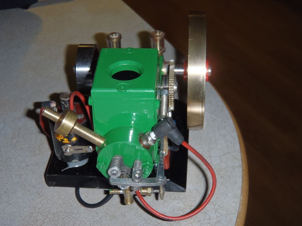
How much compression should an engine like this have.
When I turn it over, it does feel like there is some, and this is after I moved the cylinder assy. 3/16 of an inch closer to the crank than the plan said to!!, but I don''t think it is enough.
The original cyl head to top of piston was almost 3/8"..the bore is only 7/8". I have lots of spark, it fires at TDC.
I hope to add some weights and make it a H & M.
|
| Thread: Steam Locomotive timing |
| 09/10/2009 17:41:15 |
Being a "newbie" to steam locomotive construction, I am having difficulty getting my motion timed.
I have built a "Big Goods" from ME, and I have assembled it, and can run it on 1 cylinder, in 1 direction only, either forward or reverse.
I cannot figure out where the eccentrics on the drive shaft have to be in relation to the crank. The reversing lever arrangement does not appear to move enough to reverse the engine ,but just enough to stop it. I have quadruple checked all the connecting rods, links etc for length and c-c distances and everything is "as per drawings"....
A diagram of where the slide valve should be at 0, 90, & 180 degrees of crank travel would help.
I am in Canada, and have been building this, from scratch, i.e. no castings since about 1996 or so. |


Magazine Locator
Want the latest issue of Model Engineer or Model Engineers' Workshop? Use our magazine locator links to find your nearest stockist!
Sign up to our Newsletter
Sign up to our newsletter and get a free digital issue.
You can unsubscribe at anytime. View our privacy policy at www.mortons.co.uk/privacy
Latest Forum Posts
- hemingway ball turner
04/07/2025 14:40:26 - *Oct 2023: FORUM MIGRATION TIMELINE*
05/10/2023 07:57:11 - Making ER11 collet chuck
05/10/2023 07:56:24 - What did you do today? 2023
05/10/2023 07:25:01 - Orrery
05/10/2023 06:00:41 - Wera hand-tools
05/10/2023 05:47:07 - New member
05/10/2023 04:40:11 - Problems with external pot on at1 vfd
05/10/2023 00:06:32 - Drain plug
04/10/2023 23:36:17 - digi phase converter for 10 machines.....
04/10/2023 23:13:48 - More Latest Posts...
- View All Topics
Support Our Partners


Shopping Partners
Subscription Offer

Latest "For Sale" Ads
- Reeves** - Rebuilt Royal Scot by Martin Evans
by John Broughton
£300.00 - BRITANNIA 5" GAUGE James Perrier
by Jon Seabright 1
£2,500.00 - Drill Grinder - for restoration
by Nigel Graham 2
£0.00 - WARCO WM18 MILLING MACHINE
by Alex Chudley
£1,200.00 - MYFORD SUPER 7 LATHE
by Alex Chudley
£2,000.00 - More "For Sale" Ads...
Latest "Wanted" Ads
- D1-3 backplate
by Michael Horley
Price Not Specified - fixed steady for a Colchester bantam mark1 800
by George Jervis
Price Not Specified - lbsc pansy
by JACK SIDEBOTHAM
Price Not Specified - Pratt Burnerd multifit chuck key.
by Tim Riome
Price Not Specified - BANDSAW BLADE WELDER
by HUGH
Price Not Specified - More "Wanted" Ads...
Get In Touch!
Do you want to contact the Model Engineer and Model Engineers' Workshop team?
You can contact us by phone, mail or email about the magazines including becoming a contributor, submitting reader's letters or making queries about articles. You can also get in touch about this website, advertising or other general issues.
Click THIS LINK for full contact details.
For subscription issues please see THIS LINK.
Digital Back Issues


Donate

 Register
 Log-in
Model Engineer Magazine
- Percival Marshall
- M.E. History
- LittleLEC
- M.E. Clock

ME Workshop
- An Adcock
- & Shipley
- Horizontal
- Mill

Subscribe Now
- Great savings
- Delivered to your door

Pre-order your copy!
- Delivered to your doorstep!
- Free UK delivery!