Member postings for Peter E
Here is a list of all the postings Peter E has made in our forums. Click on a thread name to jump to the thread.
| Thread: Harold Hall QTCP, MEW 50, any one using it? |
| 08/12/2010 22:59:13 |
I would like some more info on the best way to use the dovetails. On my version - see separate thread "My C3 QCTP" - I have chosen to have the "male" part as part of the tool post, and the "female" part as part of the tool holder. From what I can see on Mr Stevenson´s picture above, the use is the opposite. My thinking is that with the male part being part of the tool post, it will be easier to design the dimensions so that the total overhang of the tool compared with the cross-slide is as small as possible. I will even try to mill the top surface of the C3 top-slide circular so that the tool holder can pass below the top-slide top surface. All to give the largest possible range of movement. Is my thinking correct, or am I out in the blue (as usual)  ? ?/Peter E Edited By Peter E on 08/12/2010 23:00:23 |
| Thread: My home made C3 QCTP |
| 20/11/2010 22:11:14 |
Thank you Steve and Stub M for your comments!I do not have a ball turning tool of any sort - yet - so I had to go for something else, and something that does not hurt when thumped wrong  @Stub M: Your handle design sounds interesting, do you by any chance have any photos? BR /Peter |
| 20/11/2010 18:19:44 |
Just wanted to show the first part of a QCTP I am making right now for my SIEG C3 lathe.  The design used comes originally from Ishimura and Jim Whethren, but here adapted in size to fit the C3. The main block is made from a lump of cast iron coming from an old iron (you know the type used to iron clothes and was heated by putting it on the stove). The material is very good and have no hard spots as far as I could find. The tool holder locking sleeve is BMS and the center part locking the position of the whole thing is made from a bit of hard brass, all found in the scrap bin. Made the handles in a style of my own, and intend to use the same style also for the tail stock barrel lock and the half-nut locking arm as it turned out to my liking. I will be back when I have got hold of material for the tool holders. BR /Peter |
| Thread: New MEW Digital archive - access? |
| 26/12/2009 21:54:34 |
Hi! There was supposed to be some example documents to view without having to subscribe. Where are they? I can see two out of four documents having issue beneath the images but these are not the oldest ones. File problem here as well? Best Regards /PeterE |
| Thread: A simple tapping tool |
| 14/11/2009 23:03:53 |
| Hi!! Since the visiting frequency is fairly high on this thread, I thought that I could publish a short manufacturing description as well. Unfortunately a lathe is necessary for some of the parts, but for the imaginative other solutions are probably available. The idea is to provide a little inspiration and some ideas. As a starting point I used a simple drill stand, ... 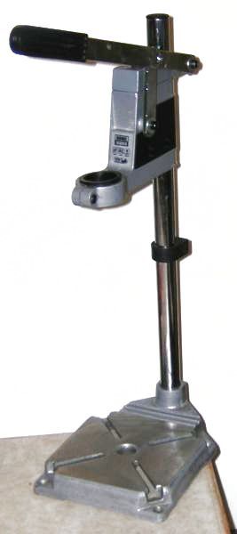 and one of those simple angle-gears for hand-held electrical drills (the chuck was nice). 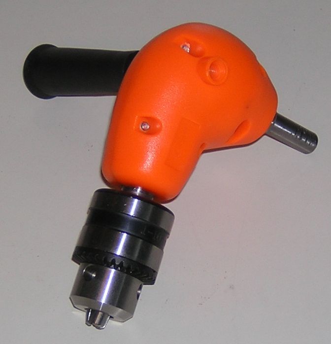 Also some parts from the famous store of odd bits-and-pieces. I did not think that it was necessary to keep the drill-stand feed function, so I removed all those parts to get a clean "head". Next in line was to make the lump that is clamped in place instead of the drill. Mine was made out of brass, but anything from cast iron to aluminium will work. 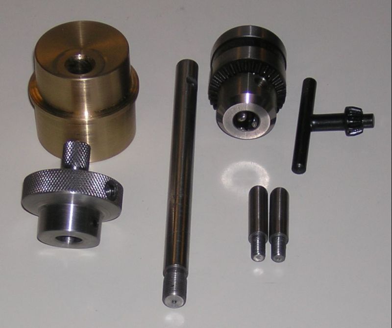 The brass block is the main part. Note that the hole for the chuck axle is off center and quite close to the outer diameter. This will give more room for the "wings". The knob in front of the block have two knurled diameters to provide suitable momentum for smaller taps. In addition I drilled two holes opposite each other (or one right through the knob) in the larger knurled portion for two stub wings as an aid for turning larger taps. There is also one cross-hole below the larger knurling for two set screws locking the knob to the axle. To the right of the knob we see the axle, 100 mm (3/8") dia and about 150 mm (6") long with a 3/8"-24 UNF thread for the drill chuck. Make the threaded portion the same as the one on the angle gear. Further to the right are the chuck key and the two stub wings. The wings are made from a piece of 8 mm (5/16") round bar with M6 or 1/4" BSW/BA thread. make the ´wings just long enough to clear the head casting with a safe distance. This is how it looks when the block is clamped in place. 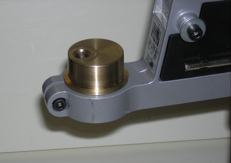 Now we add the knob-axle assembly: 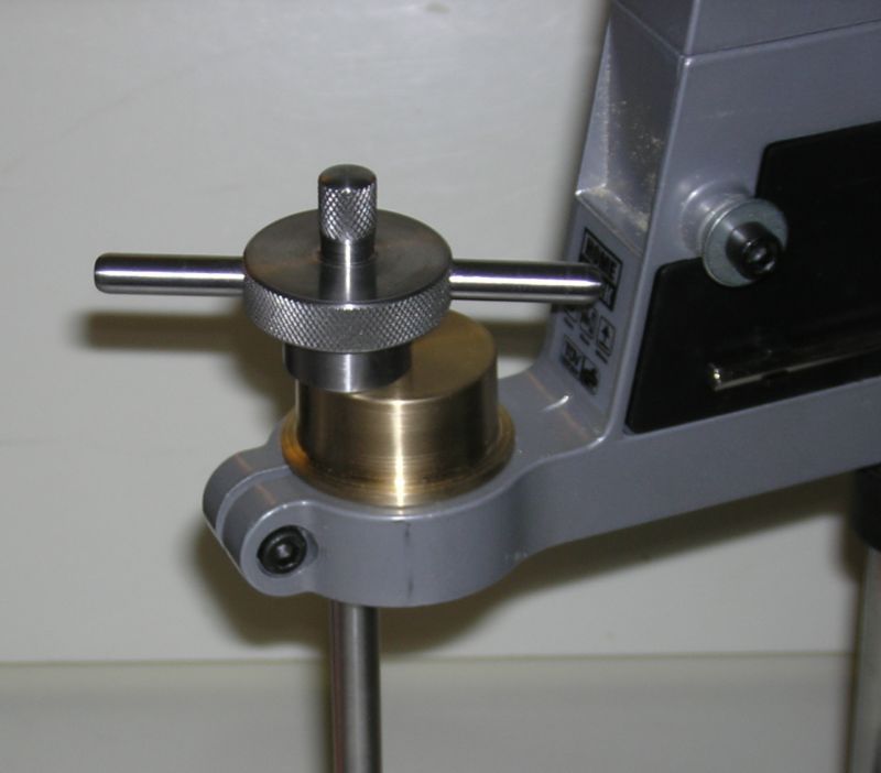 As can be seen, the wings pass the head casting quite close, but it works well all the way up to M6/M8 . Time for the chuck. 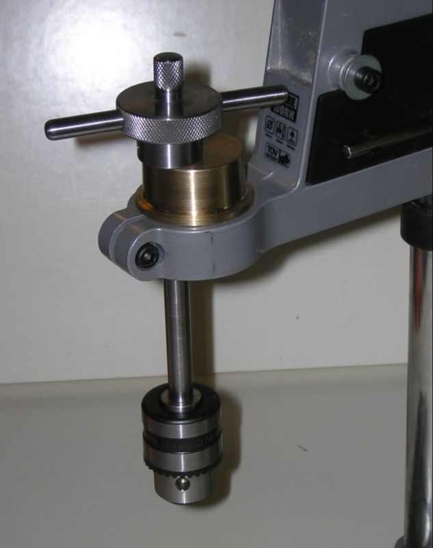 It is enough to just screw on the chuck and tighten well, but for best performance the chuck is secured with a little Loctite or similar. After some filing and finishing the whole stand is painted in your shops colour. The feeding function is locked by exchanging the guide-bar for an M10 bolt, and we get a result as shown below. The black plastic cover is replaced and on its left side (invisible here) the chuck key gets a clip to be at hand when wanted, and out of the way when working. 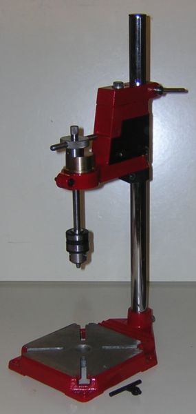 Best Regards /PeterE |
| 05/09/2009 19:50:21 |
@Bob Sims 4 The base-plate and pillar of this type of cheap drill stand is actually rigid enough to work great as a base for a George H Thomas (GHT) style universal pillar tool. I wish you good luck and hope that you can take a picture of the result  The idea to use cheap pipe fittings also crossed my mind, but before putting this simple tapping tool together, I actually made myself a slightly modified UPT according to the GHT drawings. It came out like below: 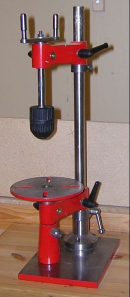 Compared with the GHT drawing, I had to change the foot as a small MJ-189 cannot "bite" over more than about 70 mm dia (2 13/16") and that was stretching it a bit. Therefore I added a 10 mm (3/8") base plate for stability. The arms came out of a piece of 32x75 (1 1/2" by 3") bar (quite a lot of hand work there), and the extra foot to support the table. Oh yes, the table. An MJ-189 only have about 45 mm center height so the table came out of an old B&D drill face plate. Apart from the above mods, all is according to the GHT drawings, readily and carefully made in steel using a small MJ-189 Best Regards /Peter |
| 23/07/2009 22:46:10 |
@ Wheeltapper: I found mine in a Coop store (in Sweden), but I guess you can find a similar one in for example Aldi or Lidl almost anywhere. As a drill stand I think it is a bit flimsy, but as a tapping stand i works great. So, I removed the feed linkage and locked the two parts together with a 10 mm (3/8") bolt. Your idea of turning the thing upside-down is good, why didn´t think of that, hmm. On the other hand, even the smaller stub handles on my version is perfectly good for tapping with 6 to 8 mm (1/4" to 5/16") taps. I decided to make the handle like a knob with two diameters for more sensitive handling for smaller taps and adding two small stubs for the larger taps. The stubs can then be screwed out so the knob can be rotated freely. @ Ian S C: Well this is one of those mini projects turning a good-to-have item into something really useful. Hope this was helpful. Best Regards /Peter |
| 18/07/2009 21:47:14 |
| Having broken too many small taps I thought it was time to do something about it. The ultimate version is the UPT (Universal Pillat Tool) by George H Thomas, but as I at the time only had a Unimat 4 clone and a small bench drill it had to be something simpler. One day I spotted a clearing sale of a drill stand to a cost of about £4! I added on a cheap angle gear for a hand held power drill as it had a nice 1-10 mm chuck with 3/8-20 UNF thread. A few hours of work and this was the result: Best Regards /Peter |
Magazine Locator
Want the latest issue of Model Engineer or Model Engineers' Workshop? Use our magazine locator links to find your nearest stockist!
Sign up to our Newsletter
Sign up to our newsletter and get a free digital issue.
You can unsubscribe at anytime. View our privacy policy at www.mortons.co.uk/privacy
Latest Forum Posts
- *Oct 2023: FORUM MIGRATION TIMELINE*
05/10/2023 07:57:11 - Making ER11 collet chuck
05/10/2023 07:56:24 - What did you do today? 2023
05/10/2023 07:25:01 - Orrery
05/10/2023 06:00:41 - Wera hand-tools
05/10/2023 05:47:07 - New member
05/10/2023 04:40:11 - Problems with external pot on at1 vfd
05/10/2023 00:06:32 - Drain plug
04/10/2023 23:36:17 - digi phase converter for 10 machines.....
04/10/2023 23:13:48 - Winter Storage Of Locomotives
04/10/2023 21:02:11 - More Latest Posts...
- View All Topics
Support Our Partners


Shopping Partners
Subscription Offer

Latest "For Sale" Ads
- Reeves** - Rebuilt Royal Scot by Martin Evans
by John Broughton
£300.00 - BRITANNIA 5" GAUGE James Perrier
by Jon Seabright 1
£2,500.00 - Drill Grinder - for restoration
by Nigel Graham 2
£0.00 - WARCO WM18 MILLING MACHINE
by Alex Chudley
£1,200.00 - MYFORD SUPER 7 LATHE
by Alex Chudley
£2,000.00 - More "For Sale" Ads...
Latest "Wanted" Ads
- D1-3 backplate
by Michael Horley
Price Not Specified - fixed steady for a Colchester bantam mark1 800
by George Jervis
Price Not Specified - lbsc pansy
by JACK SIDEBOTHAM
Price Not Specified - Pratt Burnerd multifit chuck key.
by Tim Riome
Price Not Specified - BANDSAW BLADE WELDER
by HUGH
Price Not Specified - More "Wanted" Ads...
Get In Touch!
Do you want to contact the Model Engineer and Model Engineers' Workshop team?
You can contact us by phone, mail or email about the magazines including becoming a contributor, submitting reader's letters or making queries about articles. You can also get in touch about this website, advertising or other general issues.
Click THIS LINK for full contact details.
For subscription issues please see THIS LINK.
Digital Back Issues


Donate

 Register
 Log-in
Model Engineer Magazine
- Percival Marshall
- M.E. History
- LittleLEC
- M.E. Clock

ME Workshop
- An Adcock
- & Shipley
- Horizontal
- Mill

Subscribe Now
- Great savings
- Delivered to your door

Pre-order your copy!
- Delivered to your doorstep!
- Free UK delivery!