Member postings for JasonB
Here is a list of all the postings JasonB has made in our forums. Click on a thread name to jump to the thread.
| Thread: Damaged Screws & QCTP help!!! |
| 31/07/2023 12:30:40 |
That sounds a bit low to me, from the photos I would put it closer to 25-28mm maybe check again when you are home. The tool opening in a holder is 13mm so your tool looks to be about 10mm square. Max height of the bottom of the holder is 17mm but your adjuster is a couple of mm from max so lets say 15mm. so add the 15mm and 10mm and the edge of your tool is 25mm from topslide surface. As for the nut well it only needs to be hexagonal if you want an extra spanner to loose. Simpler to go with something like you have that is cylindrical with either a fixed tommybar or just a hole for one. You could use the washer that comes with the toolpost then it is just a case of turning one end of some say 25mm bar down until it fits inside the toolpost and threading that end to suit the stud assume M8. Last thing is a hole for the tommy bar.
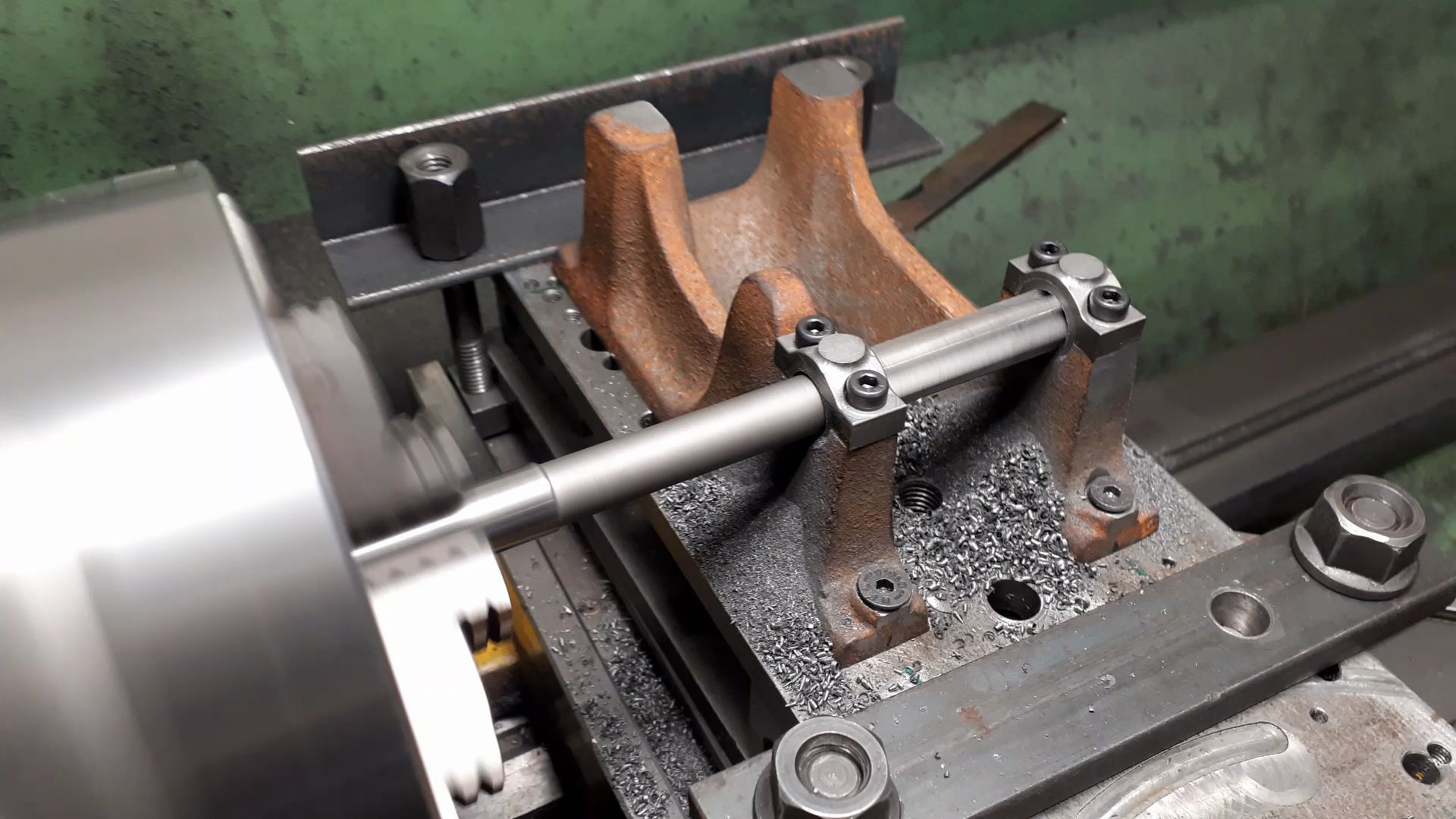
Not far off what I use on mine, the hole is drilled so I can use the chuck key to tighten the "nut"
the larger 14mm hole in the 111 toolpost gives a decent amount of metal around the M8 thread that you would not get if it had to fit the 10mm hole of the 000 size
|
| 31/07/2023 11:34:57 |
Thanks Margret.
Looking at the first photo the tool does not look like it is not yet lined up with the ctr of what you have in the chuck so could do with going up maybe another 2mm. This will put you right at the limit for that height of tool (10mm? ) and anything smaller won't really come upto ctr height without being packed up. So I would be more likely to opt for the 111 toolpost with standard holders so smaller tooling can be used. (hope the bottom ring is screwed on in that photo) The other advantage of the 111 is the hole in the middle of the toolpost is 14mm which would be better to allow the existing stud to be retained and a shouldered nut made. |
| Thread: UK Made Boilers |
| 31/07/2023 10:20:06 |
BS2790 according to their site which is "Specification for Design and Manufacture of Shell Boilers of Welded Construction" The Aussie code does specify certain construction methods, material sizes, stay spacing etc which may differ from how a boiler was designed but able to meet the BS requirements. For example I believe the Aussie code is not keen on girder stays but they would be an acceptable method of construction elsewhere.
Edited By JasonB on 31/07/2023 10:24:00 |
| Thread: Damaged Screws & QCTP help!!! |
| 31/07/2023 08:27:34 |
Thanks for those Margret, Both the QCTP you have and the 111 would work with larger tooling but the 000 may not suit the smaller sizes. To check exactly what works could you put something pointe din the lathe chuck or tailstock and take the measurement from that to the top surface of the top slide as below
Also if you could measure the diameter of the threaded portion of your toolpost stud that would help deciding what's the best way to modify that. I suspect it's an M8 thread so should be 8mm or a bit under. |
| Thread: Alibre There Eventually - Sort of |
| 31/07/2023 07:00:12 |
Posted by Nigel Graham 2 on 30/07/2023 22:34:07:
Somehow 6 holes for screws to lock them together, drilled through the larger wheel, have vanished too. Either you deleted them from the part or more likely you have edited another item up the tree on the left of the page and neglected to click "Generate to last" so the features after where you last edited are not showing I miscalculated the length of the shaft. It should be the length of the rest. I could no find no way to shorten it except by re-drawing it; but that just seemed to keep running into trouble. Lesson One: make a dimensioned paper and pencil sketch first! No need to redraw, just open up the part file again and right click on the extrusion operation where you entered the length which will open up the extrude dialogue box again and you can simply enter a revised length. Along the shaft there are: retaining collar, eccentric, an axial bearing washer, the two gears (their bearing bushes hidden), second axial washer, eccentric, collar. I have omitted finer details like the collar's grub-screws. Placing the eccentrics proved odd. I found it very hard to put in the grub-screw hole (just as plain hole); and that it worked was more luck than judgement. When placed on the shaft the first was aligned to the plane but its copy rotated itself by some random angle near 90º relatively to the first. That Component Placement tool would not act on it, and I had to pull it round into line by very tentative dragging until it looked right. If I actually make this thing I will mill seatings for the grub-screws so the eccentrics are in line. (I have no tooling for cutting internal key-ways with any certainty.) I've covered this in one of your previous posts, if in the assembly window you right click while the cursor is over the component and click "show reference geometry" that will show the three planes and axis of the given part. You can now set one of the planes relative to the main planes or that of another part be they coincident or at an angle to each other
|
| Thread: Damaged Screws & QCTP help!!! |
| 30/07/2023 20:48:38 |
Let me know the two shown
Edited By JasonB on 30/07/2023 20:48:45 |
| Thread: Quick change tool post and ball cutting |
| 30/07/2023 20:03:13 |
Margret, you do not need that flat square block at the bottom of the QCTP, should fit like this
See my comment in the stuck screw thread about heights that matter |
| Thread: Alyn RLE Last and First |
| 30/07/2023 19:02:57 |
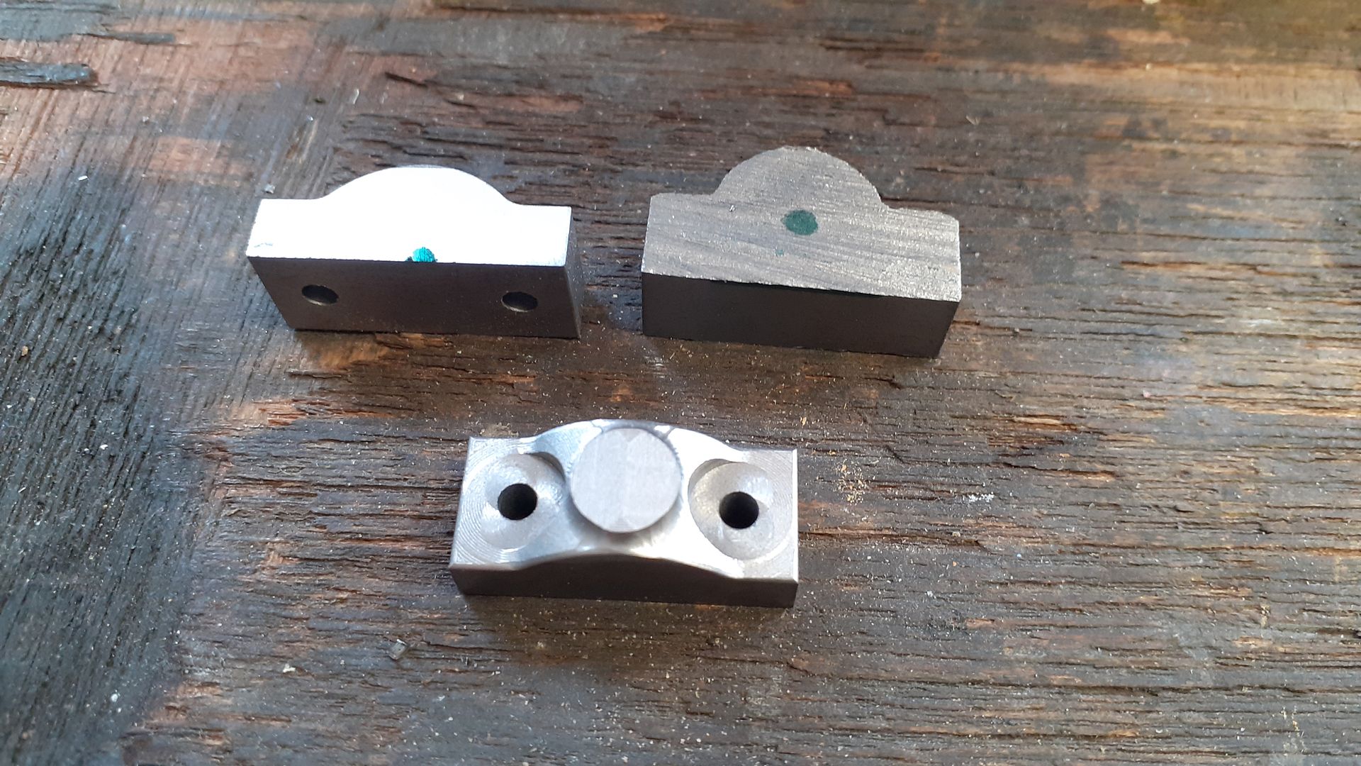
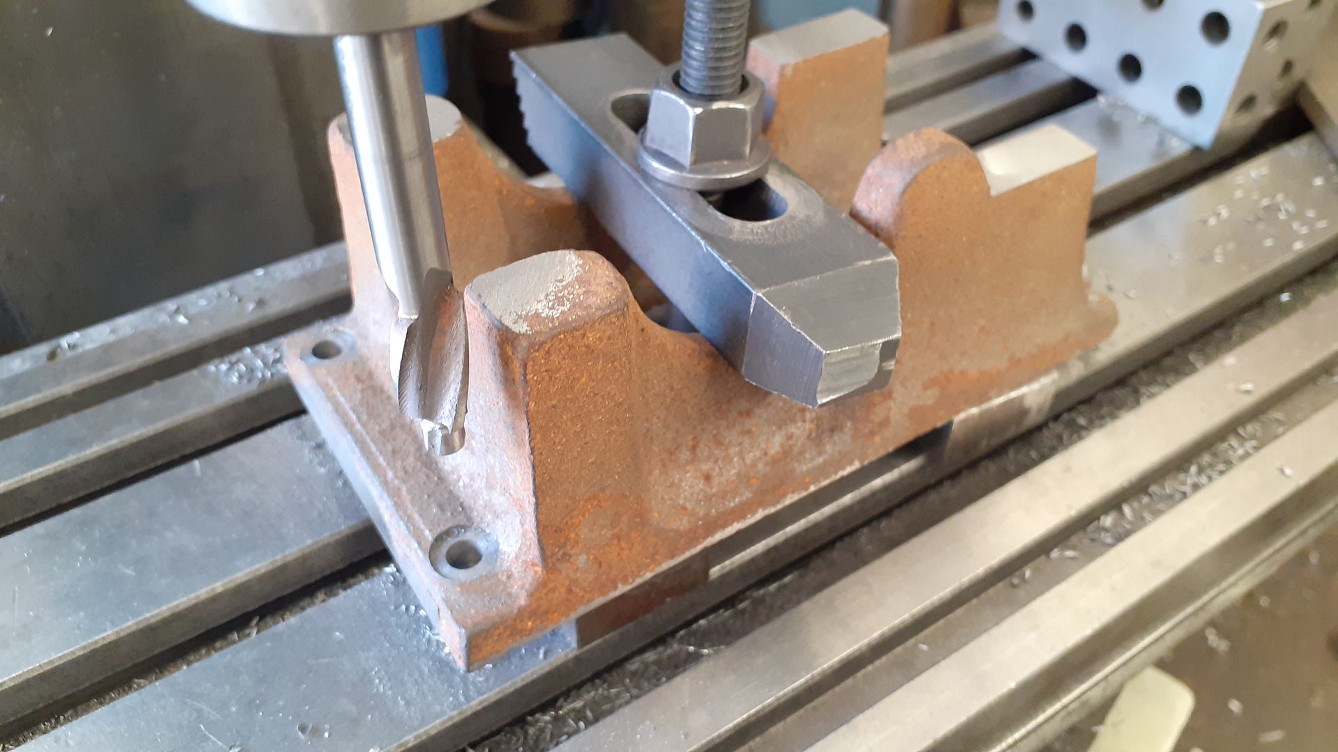
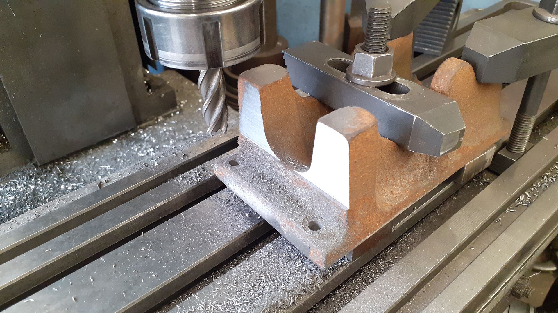
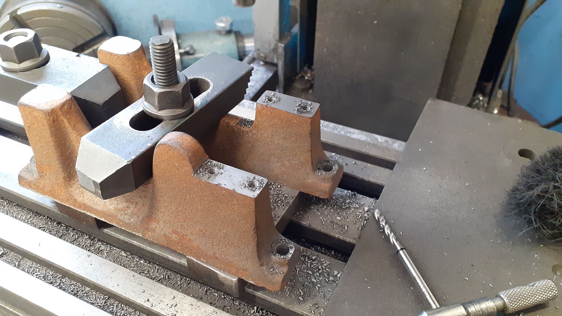
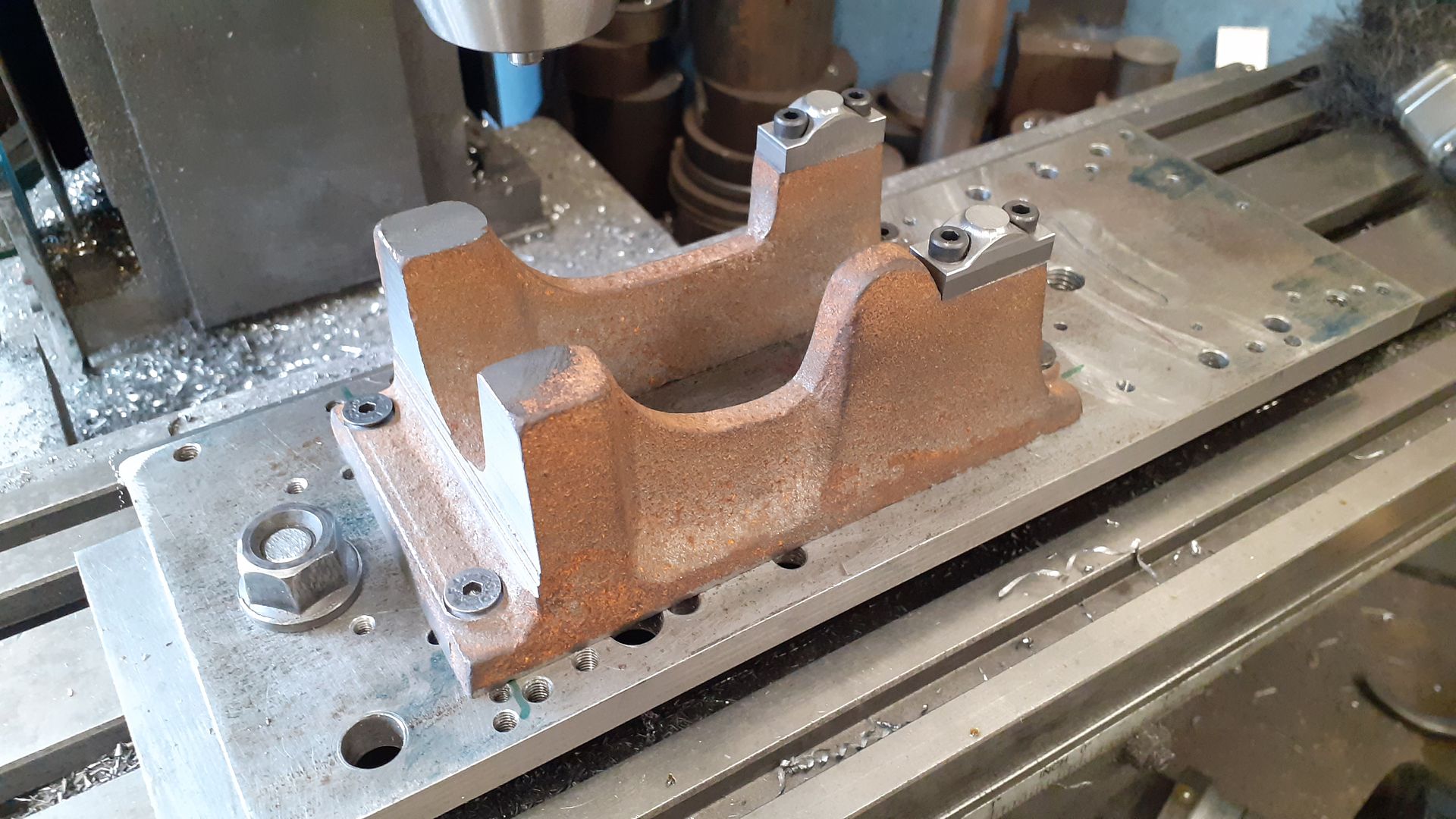
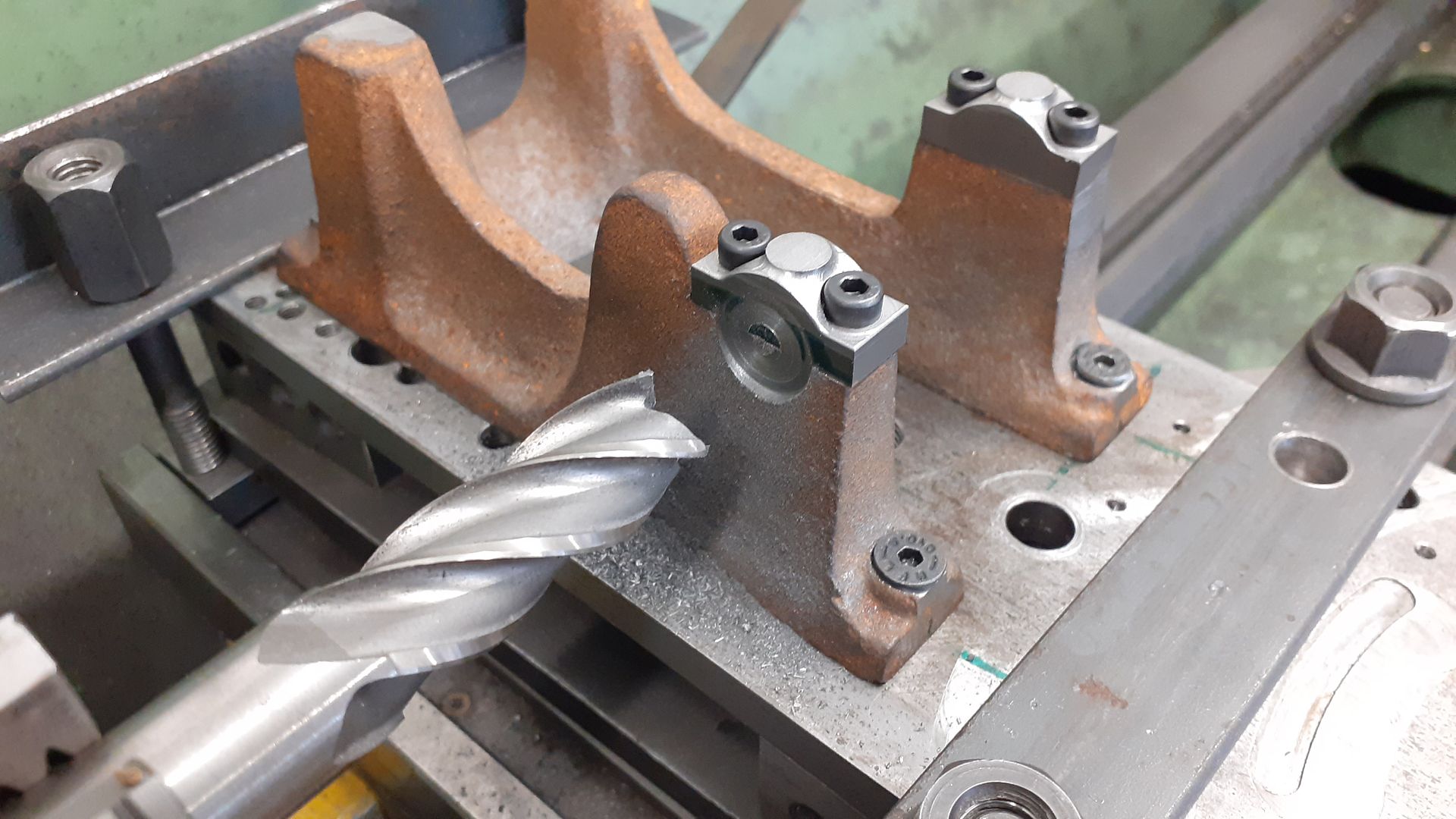
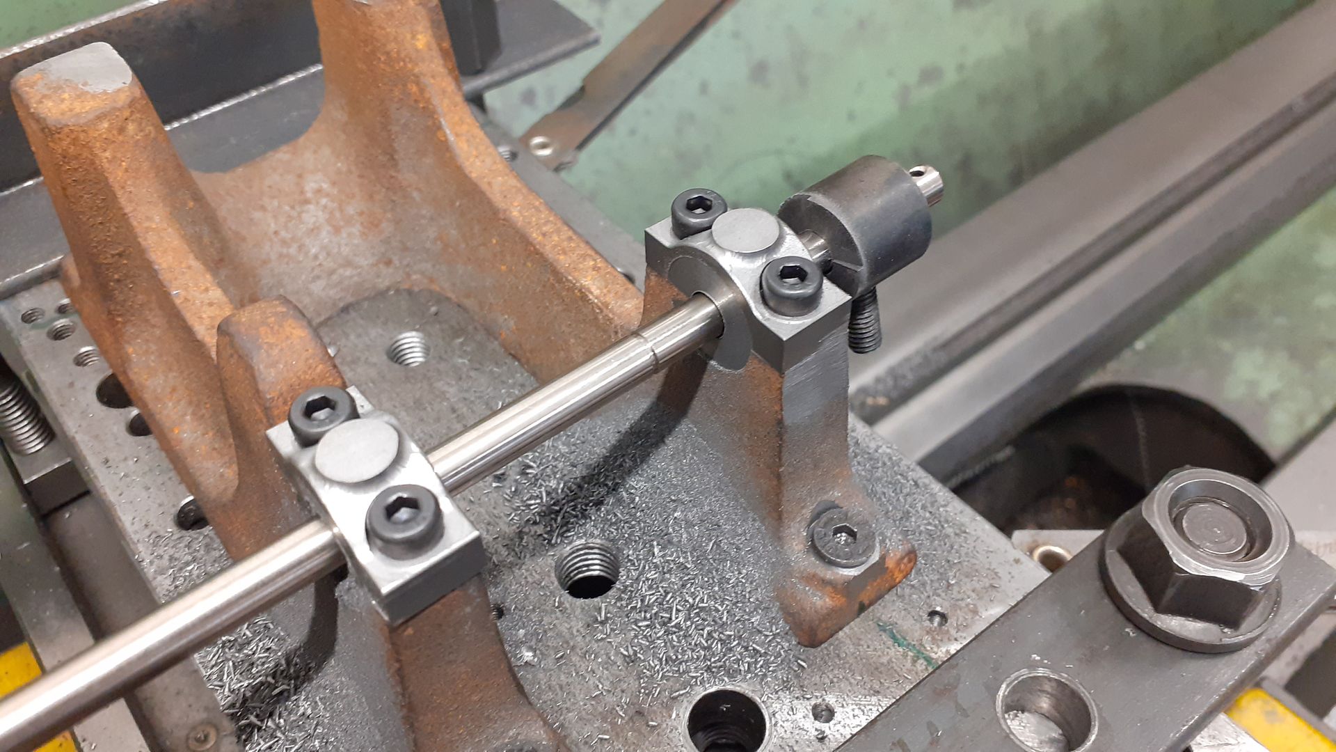
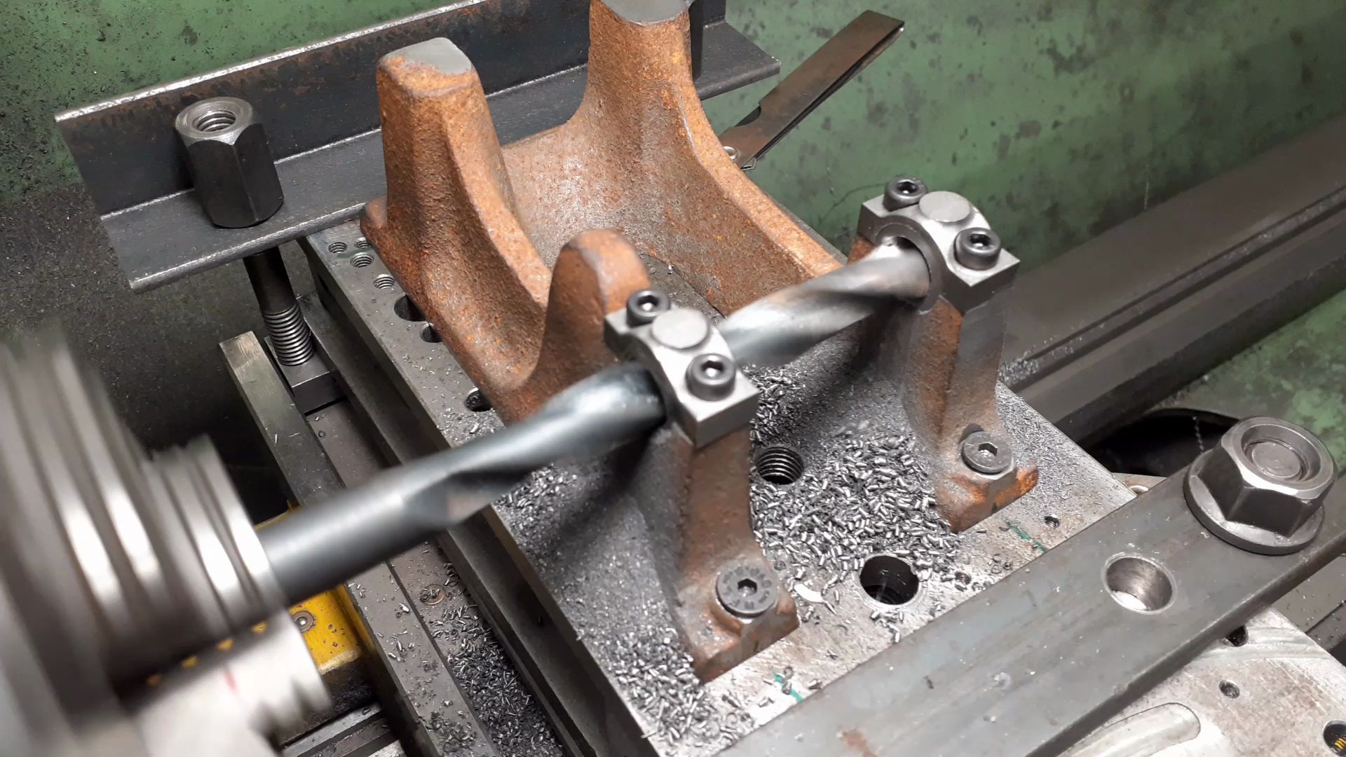
Before machining the main crankcase casting of the RLE it is worth getting the bearing caps ready. These are supplied as one so after a skim cut to flatten the bottom and then the ends with the now flat bottom against the vice fixed jaw the casting can be cut in two. Well actually you can cut it into three as there is plenty of length and it's quicker to saw away a waste piece than turn it into chips. |
| Thread: Damaged Screws & QCTP help!!! |
| 30/07/2023 13:10:01 |
Yes looks a bit short to use the existing nut. What is the diameter of the thread on the old stud, as I said a custom nut with a shoulder that will reach down into the toolpost hole may be all that is needed. Also to check the size of toolpost to suit your machine what is the thickness from bottom of the old 4-way tool post to the surface that the lathe tools rest on? |
| Thread: New Boring Head received-Questions about boring bar indexed-? |
| 30/07/2023 07:51:36 |
From previous threads on here at least some Vertex items are made in China so you may just have a Chinese boring head made there to a good spec. |
| Thread: Damaged Screws & QCTP help!!! |
| 30/07/2023 07:16:27 |
Although you may be canging posts and therefor stud I have afeeling the old stud would do.
Also although swing or ctr height of the lathe does come into it what is more important when sizing a toolpost is the distance between lathe ctr line and the top of the cross slide. Look at the details on ARC's site about how to size your toolpost and work out which will allow you to get the tools to the correct height. Supplied stud with the toolpost is I believe 10mm and threaded M10. Your existing stud looks to have a 10mm body so will pass through the toolpost unlike the Myford one which won't hence the need for a different stud. New stud looks like it might be the right length to protrude above the toolpost so at best all you would need is a large washer to replace the supplied flange nut and then tighten with your existing toolpost nut. If you short then a custom nut with extension to reach down would not be hard to make. It is quite likely that whatever toolpost you choose some alteration to the stud may be needed Edited By JasonB on 30/07/2023 08:01:43 |
| 29/07/2023 19:01:31 |
Although my lathe is larger I went and had a look, after removing the four M6 cap head screws a few taps with a copper hammer had the base ring off, it was just being held by the roll pin. I suspect the pin is only there to make sure the ring goes back in the right place as it carries the angle scale for setting the topslide at an angle.
As for the stud can you post a link to the ebay listing with the videos, I suspect you were looking at ones sold for Mini-lathes which have athreaded hole for the stud, your sis a slightly larger machine. |
| 29/07/2023 18:19:48 |
Some but not all roll pins on teh far eastern machines have an internal thread so you can put a screw in and then pull on the screw but not sure if your one will. Not sure it screws together anyway |
| 29/07/2023 16:24:10 |
STOP RIGHT THERE Margret. You don't need to be undoing those screws to get to the toolpost stud so don't worry about getting the stuck one out and put the other back. You need to wind the moving part of the top slide off the base and then you should be able to dribe the stud down & out
My bet is they are poor quality M6 x 1 x 10mm long
Edited By JasonB on 29/07/2023 16:38:25 |
| Thread: X and Y references on milling table |
| 29/07/2023 15:58:52 |
When I'm using the Vertex one with it's fixed 0-360 scale I'll often just put a bit of masking tape where it suits and mark a line against the Zero, |
| Thread: New Boring Head received-Questions about boring bar indexed-? |
| 29/07/2023 13:25:14 |
I've not found the screws on my Soba boring head mark the shanks of Brazed tip, HSS or Indexable tools so have not bothered to add any flats. Would rather have the option to tweak their position in the boring head when needed. Looks like they just sent you a lathe boring tool, the ones for boring heads tend to be a bit different Boring heads tend to be sized by the diameter of the head so you might have a 30mm head or 60mm head depending what you call width and height. Neither of which is a standard Vertex size. Edited By JasonB on 29/07/2023 13:26:56 |
| Thread: X and Y references on milling table |
| 28/07/2023 19:52:12 |
You could make a sub table with as many holes etc as you like. Having a table where the 0-360 scale can be moved saves any problems getting the slots or an edge of a part aligned to 0 or 90 (X or y) |
| Thread: Hit & Miss Engine - Help Needed |
| 28/07/2023 19:48:58 |
These engines have an atmospheric inlet so you can't do much to alter the timing on that, just the exhaust. Inlet will typically open after TDC as it needs the vacuum created in the combustion chamber to open the valve against it's light spring. |
| Thread: Fabricating a Bevel gear box - tether car |
| 28/07/2023 18:26:13 |
Other option would be a bigger pinion on the engine, as you will be doing away with the clutch that usually has the gear attached you are half way there already. Just size the axle gear to suit. Big advantage with a setup like this is you can easily change ratios which you can't do without a complete new gearbox if the angle grinder option has too low a ratio. Though tyre diameter can be brought into play. Couple of examples here, bit on gearboxes here Edited By JasonB on 28/07/2023 18:27:23 |
| 28/07/2023 16:27:12 |
I'd go with two flat side plates bored to take suitable bearings for the solid rear axle. Tap the bottom edges to fit to the chassis. Have front and rear plates that fit between the side plates the front one of which has bearings for the prop shaft I made similar years ago for a 1/8th scale buggy Quite a few tether cars run transverse engines which could be done with a belt or spur gears or if you are feeling adventurous then a slave crankshaft can be used driven by the existing crankshaft to take your two rear wheels
Edited By JasonB on 28/07/2023 16:43:29 |


![20230731_121030[1].jpg](/sites/7/images/member_albums/44290/926570.jpg "20230731_121030[1].jpg")
![20230731_080443[1].jpg](/sites/7/images/member_albums/44290/926560.jpg "20230731_080443[1].jpg")


![20230729_182710[1].jpg](/sites/7/images/member_albums/44290/926490.jpg "20230729_182710[1].jpg")


Magazine Locator
Want the latest issue of Model Engineer or Model Engineers' Workshop? Use our magazine locator links to find your nearest stockist!
Sign up to our Newsletter
Sign up to our newsletter and get a free digital issue.
You can unsubscribe at anytime. View our privacy policy at www.mortons.co.uk/privacy
Latest Forum Posts
- *Oct 2023: FORUM MIGRATION TIMELINE*
05/10/2023 07:57:11 - Making ER11 collet chuck
05/10/2023 07:56:24 - What did you do today? 2023
05/10/2023 07:25:01 - Orrery
05/10/2023 06:00:41 - Wera hand-tools
05/10/2023 05:47:07 - New member
05/10/2023 04:40:11 - Problems with external pot on at1 vfd
05/10/2023 00:06:32 - Drain plug
04/10/2023 23:36:17 - digi phase converter for 10 machines.....
04/10/2023 23:13:48 - Winter Storage Of Locomotives
04/10/2023 21:02:11 - More Latest Posts...
- View All Topics
Support Our Partners


Shopping Partners
Subscription Offer

Latest "For Sale" Ads
- Reeves** - Rebuilt Royal Scot by Martin Evans
by John Broughton
£300.00 - BRITANNIA 5" GAUGE James Perrier
by Jon Seabright 1
£2,500.00 - Drill Grinder - for restoration
by Nigel Graham 2
£0.00 - WARCO WM18 MILLING MACHINE
by Alex Chudley
£1,200.00 - MYFORD SUPER 7 LATHE
by Alex Chudley
£2,000.00 - More "For Sale" Ads...
Latest "Wanted" Ads
- D1-3 backplate
by Michael Horley
Price Not Specified - fixed steady for a Colchester bantam mark1 800
by George Jervis
Price Not Specified - lbsc pansy
by JACK SIDEBOTHAM
Price Not Specified - Pratt Burnerd multifit chuck key.
by Tim Riome
Price Not Specified - BANDSAW BLADE WELDER
by HUGH
Price Not Specified - More "Wanted" Ads...
Get In Touch!
Do you want to contact the Model Engineer and Model Engineers' Workshop team?
You can contact us by phone, mail or email about the magazines including becoming a contributor, submitting reader's letters or making queries about articles. You can also get in touch about this website, advertising or other general issues.
Click THIS LINK for full contact details.
For subscription issues please see THIS LINK.
Digital Back Issues


Donate

 Register
 Log-in
Model Engineer Magazine
- Percival Marshall
- M.E. History
- LittleLEC
- M.E. Clock

ME Workshop
- An Adcock
- & Shipley
- Horizontal
- Mill

Subscribe Now
- Great savings
- Delivered to your door

Pre-order your copy!
- Delivered to your doorstep!
- Free UK delivery!