Member postings for JasonB
Here is a list of all the postings JasonB has made in our forums. Click on a thread name to jump to the thread.
| Thread: Alibre There Eventually - Sort of |
| 02/08/2023 11:30:28 |
Placement of any hole depends on the rest of the design. No good putting your first hole at 12o'clock if you have a steam engine cylinder with the steam passages at 3o'clock unless you want a stud cutting into the passage. In a case like that first hole may want to go at 6o'clock or enter a specific angle. You can't extrude into another part within the assembly only the one you are creating or editing . You can copy and paste the hole pattern as ADY says but beware that both part swill show the same diameter rather than one clearance and the other tapping size Or you can draw them on the second part and set their position to be concentric to the holes in the first part in the assembly then if you change one layout the other will change with it and you can size each set of holes to suit. |
| 02/08/2023 10:43:15 |
Example here for anyone else interested. At the end you can see how the part created within the assembly is saved separately and a 2D drawing of just that part done. Also you can see that when I add 15mm to the width of the gear the shaft also gets extended by 15mm to maintain the 5mm projection each side. Like Andrew I don't do it that way much but each to their own Another example of how it could be used is if you have a number of gears and shafts then the casing could be created using the gear shaft positions from the assembly and if you wanted say 2mm clearance around the gears within the casing then that could be done. If you change a gear tooth count then the PCDs will automatically update as will the cavity within the gear casing to accomodate the new gear's OD. Edited By JasonB on 02/08/2023 10:43:39 |
| 02/08/2023 10:25:19 |
Andrew, the shaft does exist as a separate part. If you read my description when in the assembly screen you click "new part" which is next to insert design that you would usually use to bring in separate parts. You will then find you have the usual screen you would be using to model a separate part but also have the assembly "greyed out" so you just carry on drawing your new part but can make use of any other features of the assembly as reference points. When you then go to save you get a box come up that allows you to name your new part EG "gear shaft" and that will be stored just like a part created individually so 2D drawing easy to produce in exactly the same way. For example I could do the steam chest cover as my new part, making it's edges co-linear to the sides of the cylinder and using the stud hole pattern of the cylinder to position the clearance holes. Now the god bit is that if at some time you alter the cylinders O/A size or the stud positions then the cover will automatically get updated |
| Thread: I like a nice tool but.. |
| 02/08/2023 10:13:56 |
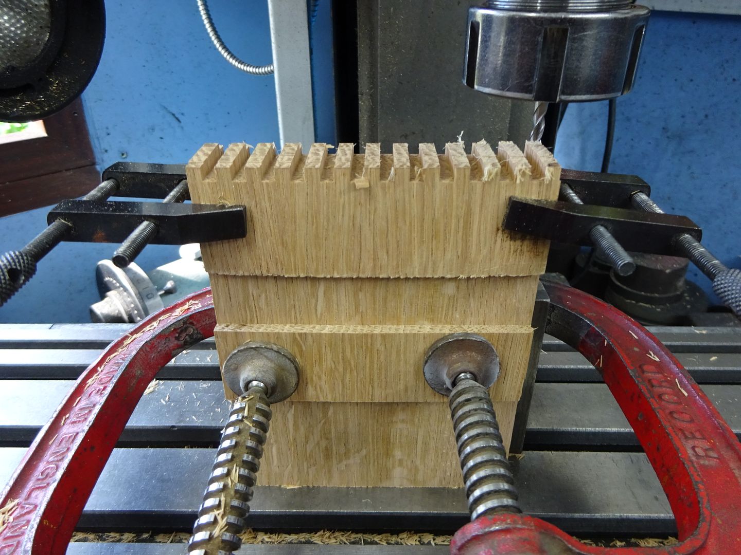
The two toolmakers clamps are holding spelch boards to stop breakout, no cut on left hand end and as I have not prestaggered the boards the right side will get cut to final height after milling. G Clamps also have packing to stop them marking the work If I do handcut then I use a japanese saw to do the vertical cuts and a standard coping saw to remove most of the waste before finishing with a chisel, when you do it to earn money sawing out most of the waste is quicker. Other options for removing the waste are to clamp say some 2 x 4 to the top of the vertically held board and use a router to cut almost to your line, the 2x4 saves the router wobbling. Most of the time for dovetails I'll use the leigh Jig, good for repetitive work like 20 draw boxes at a time. For finger joints it's quite easy to knock up a simple jig if you have a router table, a similar jig can also be used on a table saw with a flat top (zero bevel) blade and suitable guarding |
| 02/08/2023 07:55:21 |
They type of blade they hold probably makes the biggest difference as they are more like a piercing saw blade and not as high or thick as say a typical Eclipse pegged end blade. This makes it a lot easier to enter the vertical cut and then turn the blade to cut out the waste. Rigid frame does help if you get a blade going tight on the return stroke as well as being able to wind in a lot of blade tension |
| 02/08/2023 07:08:20 |
Don't think I'd want to be taking that out to site but looks nice hanging on a wall behind a pristine workbench along with a Hotley plane or two. Milling machine makes a good finger joint cutter provided your box sides are not too tall.
|
| Thread: Alibre There Eventually - Sort of |
| 02/08/2023 06:57:34 |
Posted by Nigel Graham 2 on 01/08/2023 21:54:06:
I could make it start from one face and protrude 5mm from the far face, but could not find how you would make it stick out of both faces. I tried that "dual" geometry choice but that just stuck two 5mm "discs" to the starting end. Two options there. lets assume you wanted 5mm projection each side. 1. When you create your new part first thing to do would be create a new plane 5mm from the side of gear A. Next draw your circle on that plane. Then extrude that circle and use "to geometry" selecting the far side of gear be as the target geometry and add a 5mm offset. 2. Create the shaft as two end to end cylinders. Draw a circle and extrude to geometry of gear A with 5mm offset. Then draw the same dia circle again but extrude to gear B again with the 5mm offset |
| Thread: Farm Boy |
| 01/08/2023 18:52:57 |
Looking good One point to watch is that glow and miniature spark plugs are threaded 1/4 x 32 UNEF not ME - different angle |
| Thread: UK Made Boilers |
| 01/08/2023 13:22:56 |
Hell of a lot better than my welding! Whole boiler
|
| Thread: Enjomor Hit & Miss Running! |
| 01/08/2023 10:18:58 |
Do you know what was stopping it from running? Now just need to get the governor to work so it is not running like a 4-stroke and hitting all the time |
| Thread: High Speed Milling |
| 01/08/2023 10:14:52 |
Better way to support a larger 80mm slitting saw would be two large "washers" say 60mm dia which provided they were true to a good arbor would reduce blade flex |
| 01/08/2023 10:13:14 |
To keep blade wander as small as possible you could go down to a much smaller dia blade on a part like this depending on what clearance your arbor has something like 40mm would be a lot stiffer. Might even work with a small Woodruff or tee slot type cutter. The first one showed a lot of curl, as I said I got the height wrong and top of blade was near enough level with top of work so was really just pushing up a burr. |
| Thread: UK Made Boilers |
| 01/08/2023 09:07:53 |
Thanks Paul, so Trevor would be really be better speaking to a commercial inspector rather than a club one as the larger scale steel boilers run higher pressures which really puts them outside the AMBSC code anyway so would not need to follow the construction guide lines in that code either. That is what a lot of the UK traction Engine owners do anyway as a lot of club inspectors are really only happy testing copper boilers which they have the experience with. Edited By JasonB on 01/08/2023 09:09:28 |
| 01/08/2023 08:46:37 |
Paul are you able to run commercially made boilers over 100psi with club inspection. I think they limit the WP to 100psi for home made but are the commercial steel ones covered at the higher pressures (around 180psi) or would that need an independant professional to do the inspections? |
| Thread: Alibre There Eventually - Sort of |
| 01/08/2023 08:40:27 |
At Nigel's stage of the learning curve I think it is probably better that he does as th etutorials show and draw each individual part a s aseparate file and then bring them together in an assembly. Nigelo do what is being suggested by Nick and Nealeb requires a new part to be drawn from an assembly so that certain dimensions are constrained to parts already in the assembly. Take your example and lets say start with one of the gears, draw that as a part and save. You would then need to create a new assembly and place that gear in it as your first part. Next click the "new part" tab at the top of the assembly screen and instead of drawing on a blank screen you will be drawing on a screen that already shows the gear but transparent. Lets say you want to draw the shaft next so select the plane and draw a circle which you can set concentric to the hole in the gear, close 2D and now extrude the shaft but rather than just entering a length you can select geometry which would be one side of the gear and offset 10mm from that. You now have a shaft that sticks out 10mm from the edge of the gear. If you subsequently decide your initial 12mm wide gear was too thick and want to change it to 6mm you can edit the 12mm extrusion to 6mm which will make the gear narrower. Now when you open the assembly again the gear will be it's narrower 6mm but the shaft will still be sticking out 10mm from the edge, any 2D drawing produced or measurement taken from the screen will show the reduced length of the shaft you have not had to calculate it's revised length and there is no need to go back and edit the shaft to reflect edits to the gear Had you done it as two separate parts then the shafts length would not have changed when the gear was made narrower so depending on where it was placed will end up with a different stickout and no change in length. |
| Thread: Damaged Screws & QCTP help!!! |
| 01/08/2023 06:50:50 |
Yes that is an option with the larger 14mm dia of the 111 QCTP, the one from the 10mm would probably be a bit weak by the time M8 thrad had been cut into it. A tight fit without serrations may work, possibly with some Loctite. A lot of other designs have a tight fit AND a small pin to ensure the stud does not rotate. |
| 31/07/2023 20:06:39 |
The nut would probably be the easier of the two to make,just needs to be tapped M8 (to be confirmed) for your existing stud and could just be mild steel. As could a new stud though the serrated part would be the hardest for you to make and get a good fit so that the stud does not rotate. The 000 uses an M10 thread the 111 a fine 1.5mm pitch M14 thread as standard. |
| 31/07/2023 18:43:52 |
That is an original Dickson toolpost that is mostly equipped with additional holders purchased from Chronos of no doubt of far eastern manufacture, most fitted straight away but a few needed a tweak or two. I was already on my previous lathe when I bought that so as I had a lot of holders I made it fit my Current Warco and added even more holders. Interestingly it is a bit short for this larger lathe so It sits on a square of 1/4" steel to raise it up which would be an option for you but I think the 111 would be better due to the ease of making the nut shown and by retaining the original stud you can easily use the old 4-way post for large tooling, I do that when I want to use large boring bars that won't fit the QCTP. If 22mm plus is correct then a 111 will allow you to use upto 10mm sq tooling with the standard holders or 12mm with the slim bottomed ones. You will also be able to get smaller tooling such as 3 or 4mm square HSS upto ctr height which is handy for making small form tools as the small section makes it quick and easy to grind. When you feel ready I'm sure you will get 20 different suggestions on how to make a nut like I show. |
| Thread: UK Made Boilers |
| 31/07/2023 15:23:33 |
Plate from another model boiler maker on a 2023 boiler also shows BS 2790
|
| Thread: Bum deal on Toilet Seats! |
| 31/07/2023 13:13:40 |
ideally find the make model of your pan and by the makers seat to suit that way it will be sized to have the pads in the right place to sit properly on the rim and fixings correctly positioned so you get just enough overhang to be able to get hold of seat or cover. Robert's £35 quid sounds very cheap I'm often paying £150 for ones when I'm fitting new but worth it as I don't have to go back and refix/replace. I fit quite a bit of Duravite stuff. |


Magazine Locator
Want the latest issue of Model Engineer or Model Engineers' Workshop? Use our magazine locator links to find your nearest stockist!
Sign up to our Newsletter
Sign up to our newsletter and get a free digital issue.
You can unsubscribe at anytime. View our privacy policy at www.mortons.co.uk/privacy
Latest Forum Posts
- *Oct 2023: FORUM MIGRATION TIMELINE*
05/10/2023 07:57:11 - Making ER11 collet chuck
05/10/2023 07:56:24 - What did you do today? 2023
05/10/2023 07:25:01 - Orrery
05/10/2023 06:00:41 - Wera hand-tools
05/10/2023 05:47:07 - New member
05/10/2023 04:40:11 - Problems with external pot on at1 vfd
05/10/2023 00:06:32 - Drain plug
04/10/2023 23:36:17 - digi phase converter for 10 machines.....
04/10/2023 23:13:48 - Winter Storage Of Locomotives
04/10/2023 21:02:11 - More Latest Posts...
- View All Topics
Support Our Partners


Shopping Partners
Subscription Offer

Latest "For Sale" Ads
- Reeves** - Rebuilt Royal Scot by Martin Evans
by John Broughton
£300.00 - BRITANNIA 5" GAUGE James Perrier
by Jon Seabright 1
£2,500.00 - Drill Grinder - for restoration
by Nigel Graham 2
£0.00 - WARCO WM18 MILLING MACHINE
by Alex Chudley
£1,200.00 - MYFORD SUPER 7 LATHE
by Alex Chudley
£2,000.00 - More "For Sale" Ads...
Latest "Wanted" Ads
- D1-3 backplate
by Michael Horley
Price Not Specified - fixed steady for a Colchester bantam mark1 800
by George Jervis
Price Not Specified - lbsc pansy
by JACK SIDEBOTHAM
Price Not Specified - Pratt Burnerd multifit chuck key.
by Tim Riome
Price Not Specified - BANDSAW BLADE WELDER
by HUGH
Price Not Specified - More "Wanted" Ads...
Get In Touch!
Do you want to contact the Model Engineer and Model Engineers' Workshop team?
You can contact us by phone, mail or email about the magazines including becoming a contributor, submitting reader's letters or making queries about articles. You can also get in touch about this website, advertising or other general issues.
Click THIS LINK for full contact details.
For subscription issues please see THIS LINK.
Digital Back Issues


Donate

 Register
 Log-in
Model Engineer Magazine
- Percival Marshall
- M.E. History
- LittleLEC
- M.E. Clock

ME Workshop
- An Adcock
- & Shipley
- Horizontal
- Mill

Subscribe Now
- Great savings
- Delivered to your door

Pre-order your copy!
- Delivered to your doorstep!
- Free UK delivery!