Member postings for Dr_GMJN
Here is a list of all the postings Dr_GMJN has made in our forums. Click on a thread name to jump to the thread.
| Thread: Stuart Twin Victoria (Princess Royal) Mill Engine |
| 21/06/2023 23:57:12 |
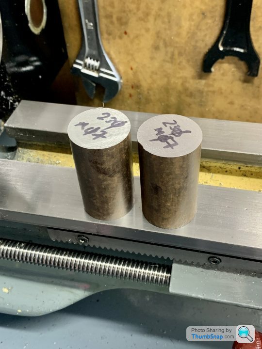
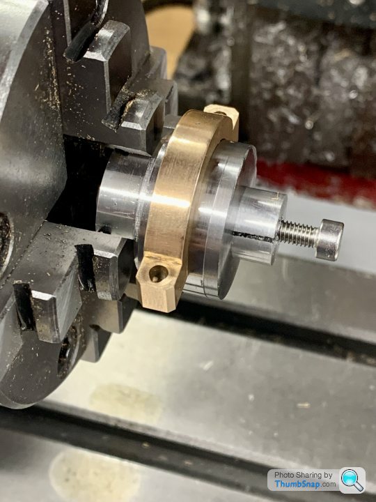
So we go again. I did a drawing, and bought some new steel bar (£3.50!) |
| 14/06/2023 21:23:38 |
So tonight I spent 6 hours on the new eccentric, only to realise that I’ve made another mistake. I left some excess on the smaller raised eccentric boss length, but then sawed it off and faced it without adding the excess. So I’ve ended up with the right overall width, but the eccentric ring is too far over. I can only think that because I’m working from both the Stuart Drawing and the Article Drawing, I’ve confused myself. For all other parts, I’ve re-drawn them and converted to metric. I think perhaps doing this lessens the chance of mistakes (for me) because I tend to calculate dimensions I know I’ll need for machining, rather than overall dimensions that need things like offsets calculating. |
| 14/06/2023 08:40:18 |
Posted by JasonB on 14/06/2023 06:56:22:
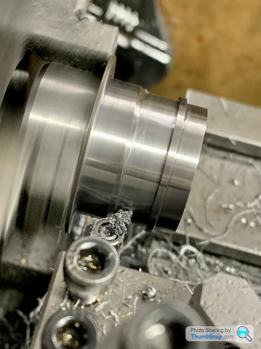
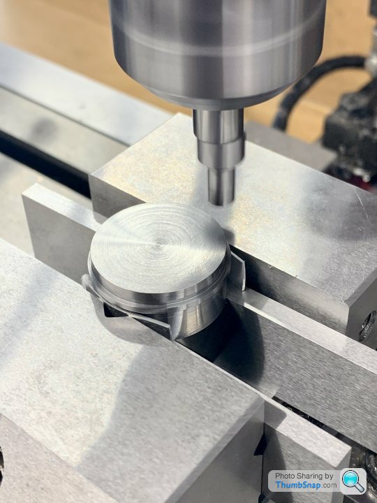
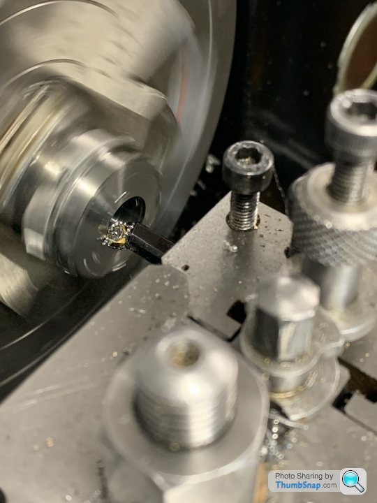
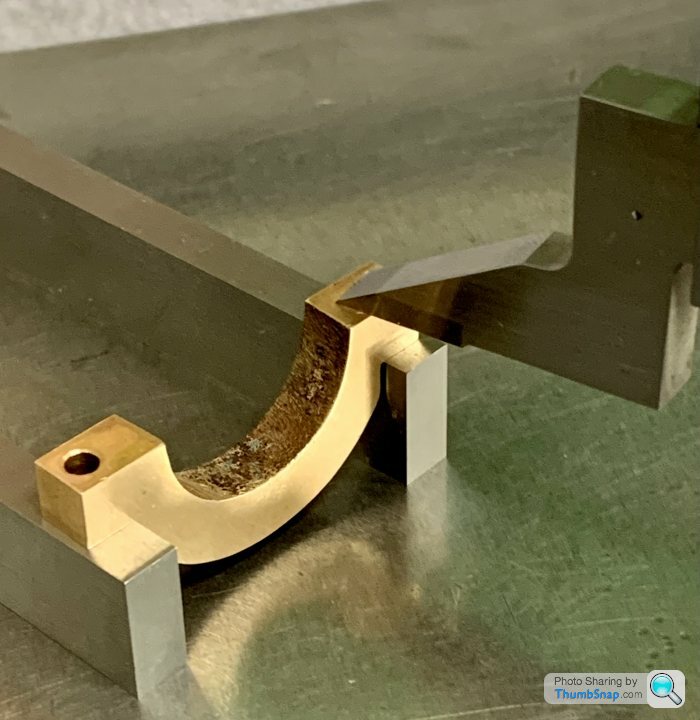
Good to see some progress. Do make sure you have allowed for the slight radius on the tip, it may be a bit tight where the arrow is pointing as that is where I usually need to ease the two corners of the strap's groove
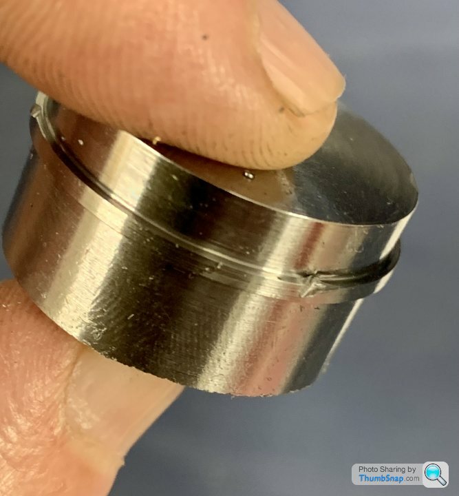
Thanks Jason. What I did there was, once everything was to the correct diameter and width, I put the point of the tool in the corner, and fed in and along very slightly to form a tiny undercut, to get rid of any radius.
by the way - I re-read your method, using a parting tool to form the diameters. I tried this, but couldn’t get the edge of the tool to cut along its length simultaneously. Moving side-to-side would help, but right next to the raised ring would have been slightly tapered. In the end I used r/h & l/h turning tools, which seemed to work ok. Edited By Dr_GMJN on 14/06/2023 08:45:24 |
| 13/06/2023 23:12:31 |
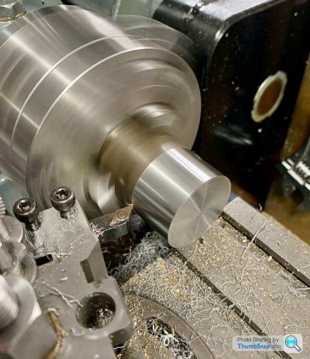
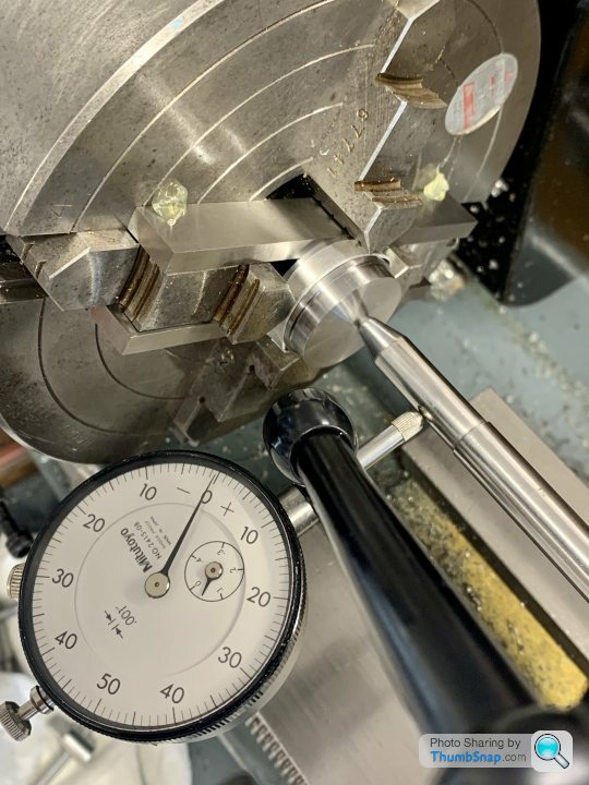
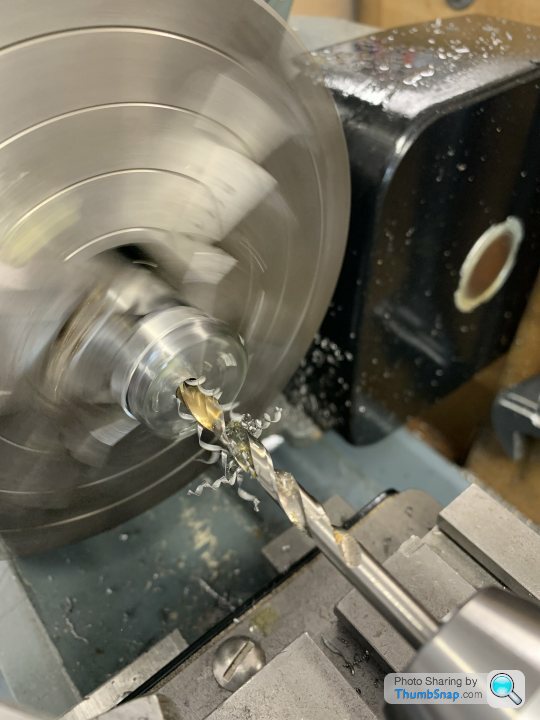
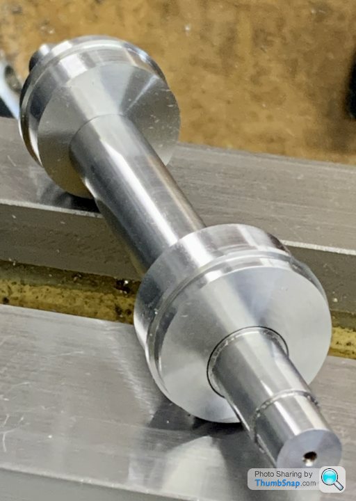
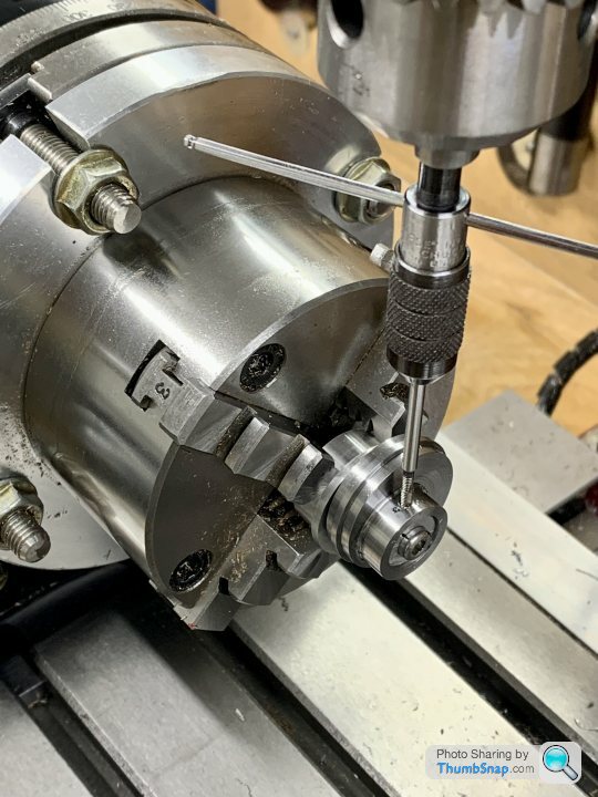
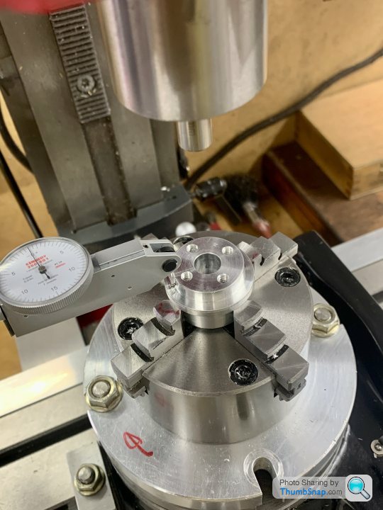
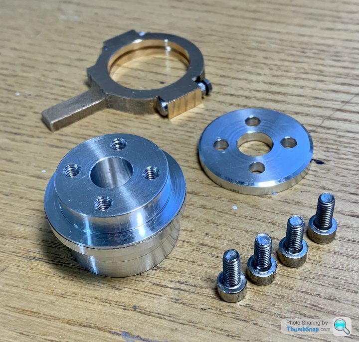
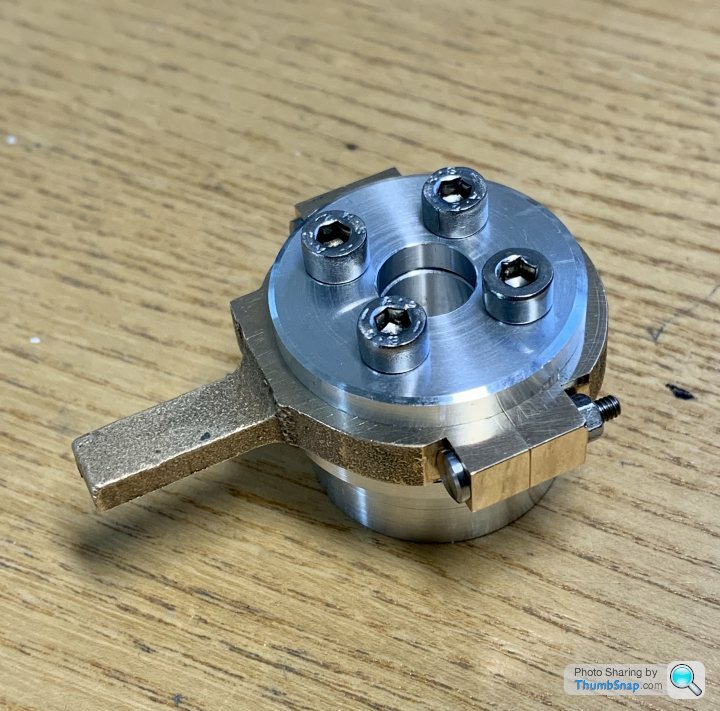
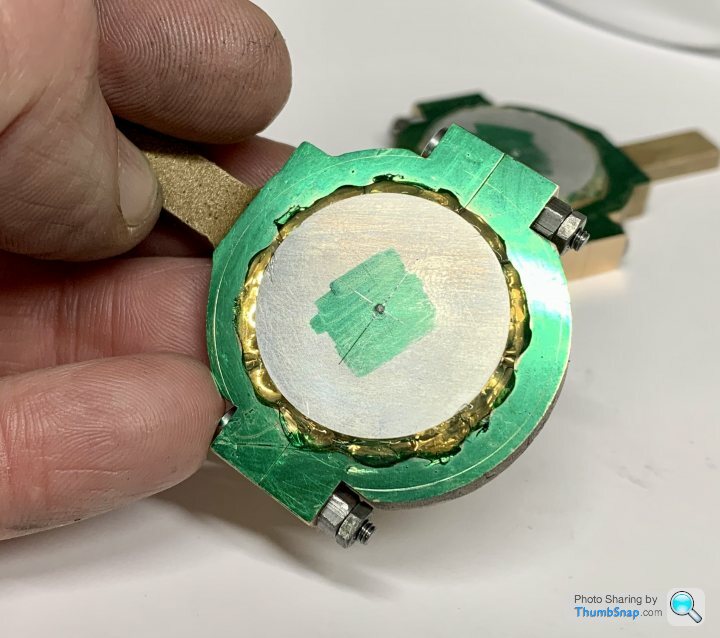
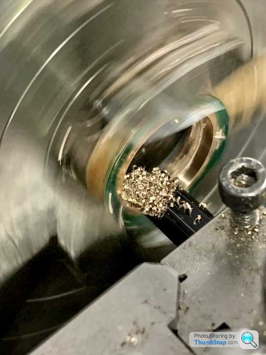
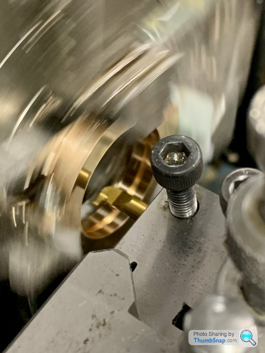
Started on the eccentric sheaves. Turned down some mild steel to the locating ring diameter: |
| 11/06/2023 22:13:08 |
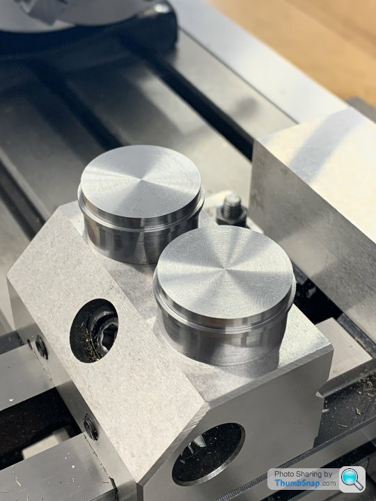
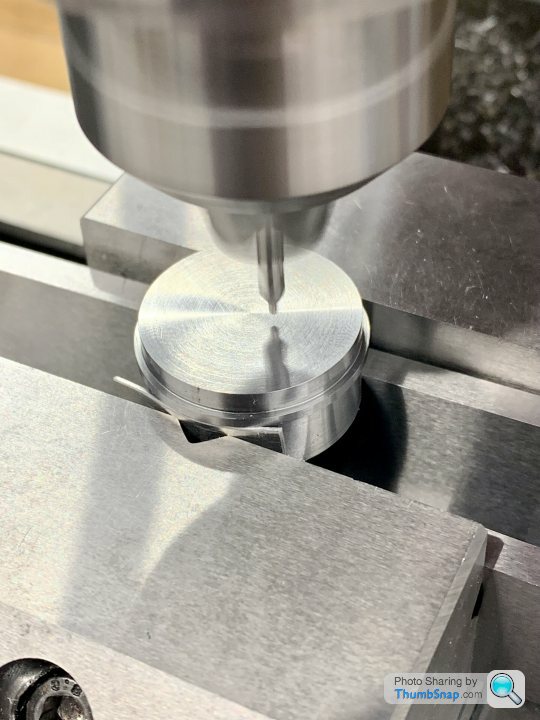
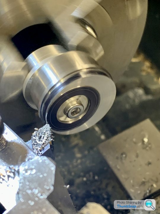
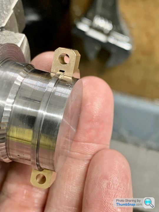
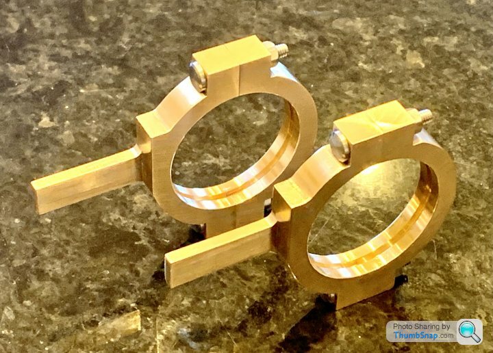
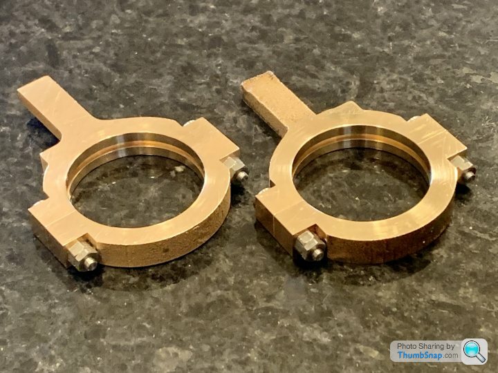
I wasn’t 100% happy with one of the eccentric strap profiles back in March, and I lost a bit of motivation to make another - they had taken a great deal of time and effort (even to get one slightly wrong!). Anyway, three months later I’ve finally made another, which is spot-on. Also added chamfers to the edges to neaten the bosses up. Just need spot-facing and drilling for the oilers, and they will both be done. Strange how this one took less than a day, the previous ones took a week or more of messing about. Even considering not having to re-make the r/t fixture, I guess that shows the time it takes me to try and figures things out, plus chasing mistakes. |
| 19/04/2023 11:08:40 |
Posted by JasonB on 19/04/2023 10:30:41:
That looks good Doc, what made you change to the smooth faced flywheel?
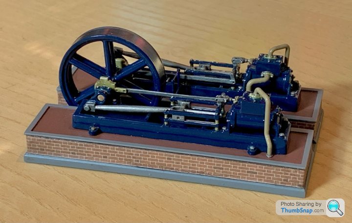
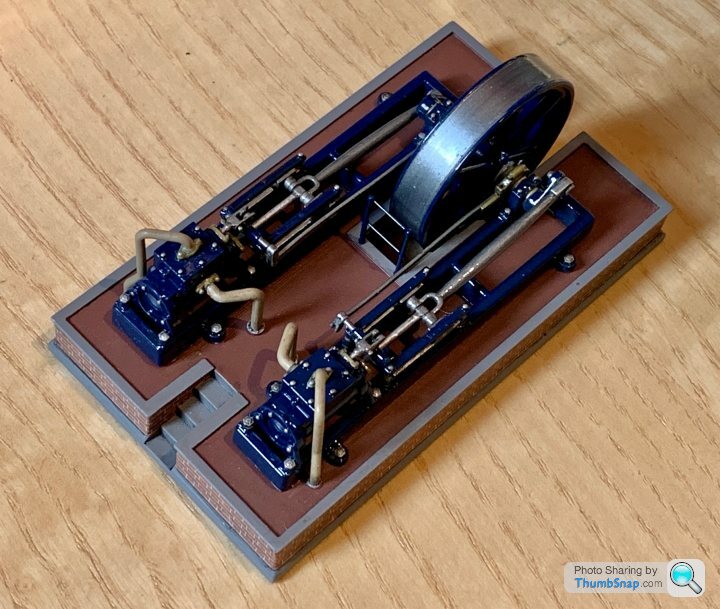
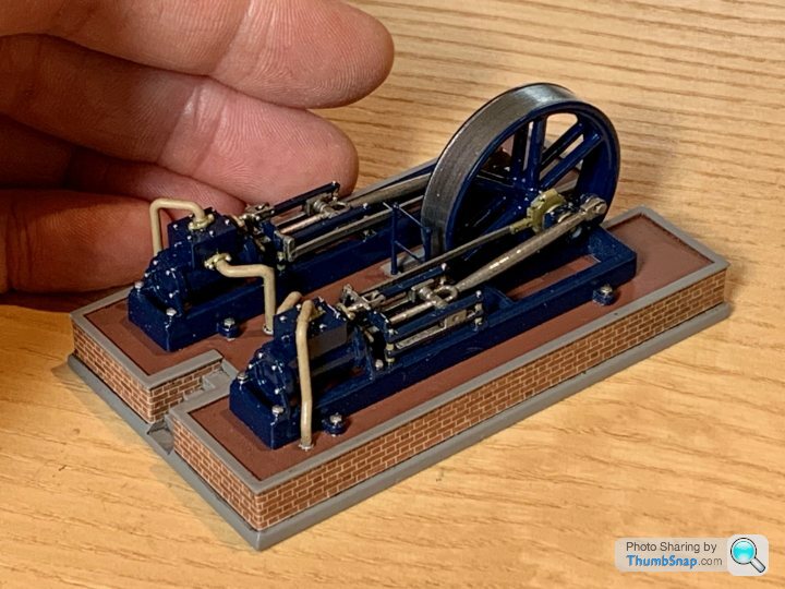
Thanks Jason, We ended up making it smooth because the grooves were tiny, and no reasonably sized band would fit. So I turned the grooves off on a mandrel, and formed a recess which both trued the wheel a bit, and made it more suitable for the drive belts that we had.. |
| 18/04/2023 22:16:26 |
It’s finished! Edited By Dr_GMJN on 18/04/2023 22:17:19 |
| 03/04/2023 16:22:53 |
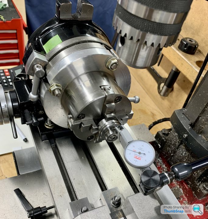
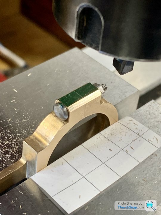
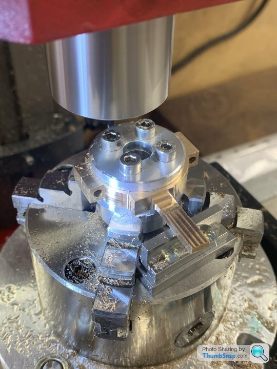
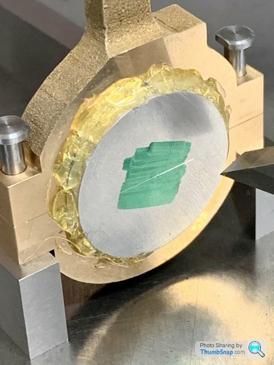
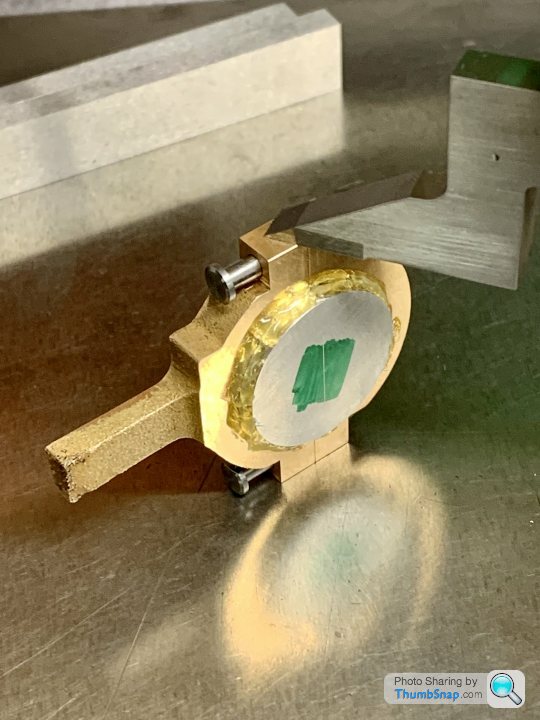
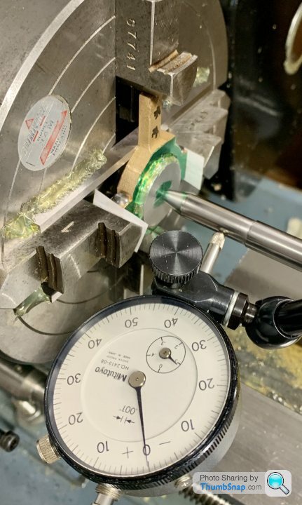
Set the fixture in the R/T: |
| 02/04/2023 14:36:59 |
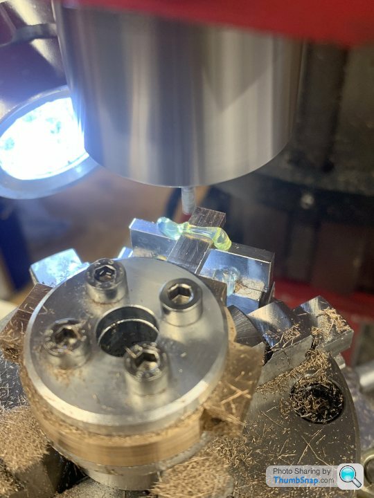
Made the fixture for milling the outside profile: |
| 01/04/2023 15:25:33 |
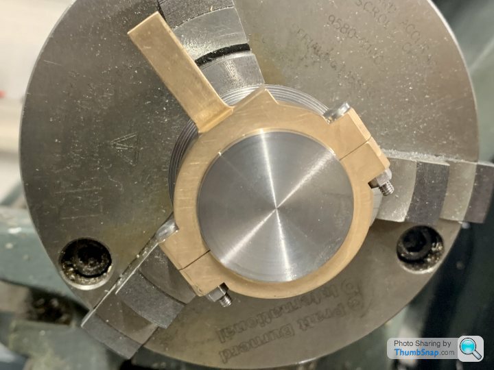
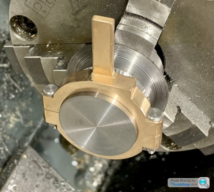
Continued with the straps this morning, marking out for setting up in the 4-jaw chuck: |
| 31/03/2023 23:08:12 |
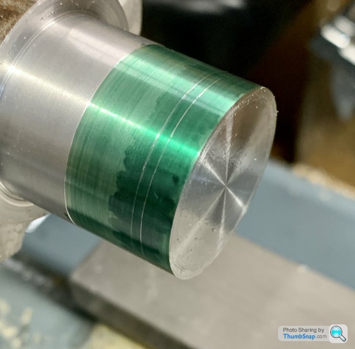
I’ll hopefully get to making the eccentrics this weekend. I’ll give the parting tool method a go, although judging the right diameter I think I’ll find tricky. I’m thinking I might turn the outer side of the ridge first, checking fit with half the strap overhanging, then when it’s spot-on, measure and machine the chuck side to the same measurement. |
| 31/03/2023 23:07:17 |
I’ll hopefully get to making the eccentrics this weekend. I’ll give the parting tool method a go, although judging the right diameter I think I’ll find tricky. I’m thinking I might turn the outer side of the ridge first, checking fit with half the strap overhanging, then when it’s spot-on, measure and machine the chuck side to the same measurement. |
| 31/03/2023 14:49:40 |
I guess the reason for the separate central ring is to make machining to a good fit easier, since the eccentric boss can be turned in one pass rather from each side? Presumably though because of the fitted bolts and lock-nuts, a tight fit can to some extent be compensated for?
|
| Thread: Fash? |
| 31/03/2023 14:27:30 |
Thanks guys, I couldn't find much online, but if's in the OED with a description that matches what I was talking about, then as far as I'm concerned "Fash" is a valid term to use for a rough edge. And "Flash" is reserved for excess material outside a mould or die. So the first teacher (and my Dad) were right, the second teacher was wrong. Sorted! |
| 31/03/2023 00:19:38 |
Posted by duncan webster on 30/03/2023 23:58:50:
One of #2 son's practice maths GCSE exam papers gave one equation with 2 unknowns, and he was meant to solve it. The maths teacher would not have it that there were an infinite number of solutions, because 'the exam board wouldn't have got it wrong'. I could give other examples of silly exam questions, but I've bored you enough already.
And we always called rough edges from cutting 'rags', but I have seen drawings with 'frase all edges'. Edited By duncan webster on 30/03/2023 23:59:49 Edited By duncan webster on 31/03/2023 00:01:54 The big dilemma during his engineering revision was sometimes whether to accept what was written in his exam revision notes, or to go with the correct answer. |
| 30/03/2023 23:14:34 |
Posted by Roderick Jenkins on 30/03/2023 21:56:52:
Posted by Peter Greene 🇨🇦 on 30/03/2023 21:24:33:
My OED gives one meaning of "fash" as: "A rough edge or ridge left on nails, cast bullets, etc" It gives a second meaning as: "A fringe; anything resembling a fringe". I can't help thinking that if used in an exam answer it would be marked down as a spelling mistake Rod I think you would be shocked at the incorrect answers which are marked as correct, and vice-versa. Also some of the dodgy things… For example, in my experience, the hole centre distance of a car engine’s connecting rod doesn’t equal the stroke length. Of course, I’m mistaken. |
| 30/03/2023 21:11:18 |
It’s strange that “Fash” was used by both the teacher (2023) and my Dad (197x), both for engineering type things. I always understood “Flash” only applied to processes that used a split mould.
|
| 30/03/2023 20:45:56 |
Bit of a random one… I’m helping my son with his GCSE Engineering. He’s been told by one teacher to use the word “Fash” for what I would call a “burr”. Another teacher told him it was wrong, and to use the word “Flash” for the same thing. I’m not so sure that’s right? I remember my Dad used to use the word “Fash”, IIRC for excess thin plastic on model kits (presumably he meant “Flash&rdquo Thoughts? Thanks.
|
| Thread: Small Ground (GT) Inserts? |
| 30/03/2023 18:47:00 |
Jason, yes, once I’ve found something that works, I’ll stick with it. As you know I find HSS tool grinding a massive pain in the arse, and will only do it as a last, last resort. I don’t use the GT inserts for fly cutting, but for most other things they seem to give a good finish and I find them nice to use so…why not? I know the experts might disagree on where and when they should be used, but there we go. |
| 30/03/2023 00:04:08 |
Posted by Clive Brown 1 on 29/03/2023 22:00:53:
I think the "bluntness" referred to by the OP is the cutting edge of the SCMT insert, not the nose radius. SCGT inserts, primarily for non-ferrous metals, are considerably sharper on the cutting edge. Correct. |


 . He was a very good intuitive engineer, so I wonder if “Fash” is indeed an established term for a burr or other thin piece of excess material? Can it be used for I.M., Casting and general engineering, or…what?
Magazine Locator
Want the latest issue of Model Engineer or Model Engineers' Workshop? Use our magazine locator links to find your nearest stockist!
Sign up to our Newsletter
Sign up to our newsletter and get a free digital issue.
You can unsubscribe at anytime. View our privacy policy at www.mortons.co.uk/privacy
Latest Forum Posts
- *Oct 2023: FORUM MIGRATION TIMELINE*
05/10/2023 07:57:11 - Making ER11 collet chuck
05/10/2023 07:56:24 - What did you do today? 2023
05/10/2023 07:25:01 - Orrery
05/10/2023 06:00:41 - Wera hand-tools
05/10/2023 05:47:07 - New member
05/10/2023 04:40:11 - Problems with external pot on at1 vfd
05/10/2023 00:06:32 - Drain plug
04/10/2023 23:36:17 - digi phase converter for 10 machines.....
04/10/2023 23:13:48 - Winter Storage Of Locomotives
04/10/2023 21:02:11 - More Latest Posts...
- View All Topics
Support Our Partners


Shopping Partners
Subscription Offer

Latest "For Sale" Ads
- Reeves** - Rebuilt Royal Scot by Martin Evans
by John Broughton
£300.00 - BRITANNIA 5" GAUGE James Perrier
by Jon Seabright 1
£2,500.00 - Drill Grinder - for restoration
by Nigel Graham 2
£0.00 - WARCO WM18 MILLING MACHINE
by Alex Chudley
£1,200.00 - MYFORD SUPER 7 LATHE
by Alex Chudley
£2,000.00 - More "For Sale" Ads...
Latest "Wanted" Ads
- D1-3 backplate
by Michael Horley
Price Not Specified - fixed steady for a Colchester bantam mark1 800
by George Jervis
Price Not Specified - lbsc pansy
by JACK SIDEBOTHAM
Price Not Specified - Pratt Burnerd multifit chuck key.
by Tim Riome
Price Not Specified - BANDSAW BLADE WELDER
by HUGH
Price Not Specified - More "Wanted" Ads...
Get In Touch!
Do you want to contact the Model Engineer and Model Engineers' Workshop team?
You can contact us by phone, mail or email about the magazines including becoming a contributor, submitting reader's letters or making queries about articles. You can also get in touch about this website, advertising or other general issues.
Click THIS LINK for full contact details.
For subscription issues please see THIS LINK.
Digital Back Issues


Donate

 Register
 Log-in
Model Engineer Magazine
- Percival Marshall
- M.E. History
- LittleLEC
- M.E. Clock

ME Workshop
- An Adcock
- & Shipley
- Horizontal
- Mill

Subscribe Now
- Great savings
- Delivered to your door

Pre-order your copy!
- Delivered to your doorstep!
- Free UK delivery!