Member postings for Richard Kirkman 1
Here is a list of all the postings Richard Kirkman 1 has made in our forums. Click on a thread name to jump to the thread.
| Thread: Colchester Student Mk1 Won't Start |
| 13/12/2019 20:32:40 |
Posted by Stuart Bridger on 13/12/2019 18:49:51:
My money would be on the converter not having enough oompf. The "phantom" 3rd phase approach of thesedevices is not ideal. Also if it as not been run for a while, ltet it warm up for a while before trying the top speeds. It may need the oil needs warming up. When I first got my Chipmaster it wouldn't go a full pelt (3000 rpm). A couple pages ago A guy called Mal said that he ran his colchester student on a static converter for 4 years before it gave up. He said that it slowly lost energy and ended up not being able to get into the higher speeds. Especially given that the motor is only 1.5hp with a 3.5hp converter, surely 2hp extra is more than enough? I bought the converter from the reduced section in machine mart, so it could have been used before. It's definitely not brand new. So possibly that could be the issue, in which case i'll have to try and take it back to machine mart and get a working one? As far as warming up goes, i'll try that tomorrow as the lathe has not been used for potentially years. ive had it since august and only just been able to turn it on. The motor may not be the full issue, but could definitely do with some care. Its 65 years old and judging from how dirty the lathe is, It's probably full of crap too |
| 13/12/2019 18:15:01 |
On second attempt, trying every speed, it seems to be able to get into most but the higher speeds. Also running the phase converter at full 3.5hp instead of the 2hp stated before It doesn't seem to want to get up to speed when the 445 speed is set I'm not sure what condition the motor is in, Its the original from 1955 so it could be knackered? But, also the phase converter may be old already since I bought it from the back reduced section of machine mart |
| 13/12/2019 16:10:49 |
The lathe is alive. I spent quite a while using a multimeter testing for continuity in the circuitry, however I couldn't find anything wrong except from the way someone has changed the wiring. They have changed it so it no longer has the safety features, so the key switch, switch in the left of the headstock for the gear cupboard and others don't affect it. No longer has a no volt release either. So I had a play with the wires in the isolator, swapped two of the phases round and it worked. Someone suggested this a while ago. However, even though the lathe is now spinning a bit, it's still not happy about it. Phil, I mentioned that your lathe spun a lot more easily than mine did, I think there's too much resistance as the static converter is struggling to power the lathe. The converter has different power settings, from 0.5 to 3.5hp. but it works best on 2hp for the 1.5hp motor. I'll get some footage of the lathe on different speeds and the effect it has on the converter and post it later. I took the brake apart and it's not causing any resistance (apart from when pushed). Any thoughts? Videos to follow |
| 12/12/2019 18:29:41 |
Been back to have a play today, had a look inside the "limit switch" and it doesn't look the same as Phils. Thoughts?(apart from it being filthy)
|
| 07/12/2019 13:53:16 |
Posted by Phil Whitley on 05/12/2019 14:40:50:
Hold the bus!! I have just looked at the PDF of a Colchester Clausing manual, which states that the limit switch has THREE positions, and having now tested mine, find this is correct! there is an intermediate position where the red and blue remain connected together till the handle moves past the mid position, and the overcentre spring mechanism jumps from the bottom pair of contacts to the top pair (see pics above, which need rotating 90 deg) The clausing manual has a better wiring diagram, but I need to check out some of the none SI symbols to confirm it is the same. Phil So what does each position do to the circuit. It's the part from the no volt release sort of bit, the ring with the key and cover and stuff, so is the intermediate position where we lifted the handle and it only beeped for a second and stopped after the handle was raised further? Also, I've sent my flatmate back to Driffield with something I've made for you. Nothing too special, but you can always heat your workshop with it if not. Thanks |
| 29/11/2019 00:01:16 |
Posted by Phil Whitley on 28/11/2019 21:14:38:
well richard here is the internals of mine, for what its worth !(not a lot as it is different), the start stop lever does work as I said earlier, if you put power on to the lathe with the start lever in the up position, the pump will run, but the main motor will not, until you press the handle down then lift it up again.
Looking at the pics of your contactor,The three black wires connected to the terminals to the right of the three pin plug, on the overload coils, go to the motor, the three blue wires connected to the other side of the overload coils are the feed from the contactor. You should, with a multimeter, be able to test three seperate phase wires from the isolator switch (check the action of the switch to make sure all three blades are going in to the contacts properly) on the back, through to the three pin socket in the back of the control box, then test from the pinsof the "plug" part to the rotaty switch , out of the switch to the contactor, from the other side of the contactor to the overloads, and then on to the motor, via the reversing switch. The missing contact on the contactor is irrelevant for now, as the contactor is not even pulling in, and it should do this even if it only ends up sending two phases to the motor because of the missing contact. When you have established that three phases are getting to the input side of the contactor, check that you have continuity through the contactors operating coil, and then you will see that one side of the coil is connected directly to a phase and the other end of the coil goes off to the safety switches on the gearbox end cover, and then to the "limit" switch on the back of the headstock, which completes the circuit to pull in the main contactor. Looking at the oily state of the limit switch that could be full of muck and oil, and not making contact, take the lid off and check it, I am going to try to post up the wiring diagram from my lathe, although the contactors are different, they are electrically identical, and this diagram is somewhat easier to read and understand.
Phil Thanks Phil, I think I'm starting to understand a bit the stuff you're saying. I've responded to your message, so there should be something in your inbox. Thanks |
| 27/11/2019 22:28:11 |
Posted by Phil Whitley on 27/11/2019 20:47:28:
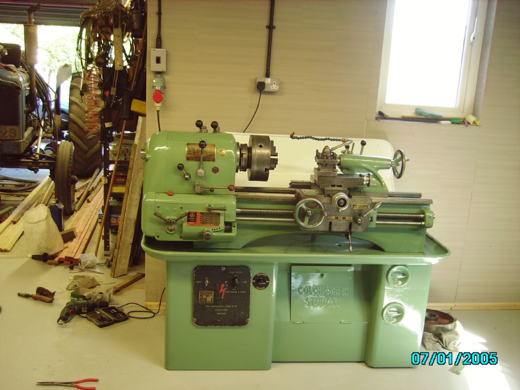
Right Richard, that is the same as mine, save for the fact that yours is earlier, and has the flat cast iron gear handles, mine has all rod type handles. The pic of the contactor panel is exactly what I wanted, I will look it over and get back to you, meantime I have messaged you, if you look at the top bar of the page, you will see a little envelope flashing! Your lathe has a hole near to the top right hand corner of the electrical panel, this is where the dual speed motor switch was fitted, I wonder if the motor has been changed? I thought this hole was only drilled when needed, which would indicate that yours was once a dual speed motor. Yours is gap bed, mine is straignt bed, Mine has the two speed motor, and needs new main spindle bearings, which luckily, I have! very original looking machine. We will have it running, one way or another! The picture of the lathe appears to show a hole, but its just a small sticker that has a 1 on it So I'm pretty certain that it has never ever been dual speed. The motor is definitely original too, so I don't think its a possibility. And yes, I watched a video of someone dismantling a similar lathe and repairing it, but the circuitry was different as it was a later model similar to yours. At about 9:10 you can see the inside of his lathe and there is a better video of a crabtree here But, i couldn't really see how it worked compared to my model
|
| 27/11/2019 20:41:30 |
Posted by Swarf Maker on 27/11/2019 20:32:39:
Well, I see the nice new cable with its plug going into the big switch box. What I don't see are any wires coming from the output contact set of that switch and into the lathe itself. Are they routed through the backplate of that switch? There is a hole for the wires to come out but nothing visible. Yeah they go out the back into the casing, don't have any pictures of where they go. Not too sure if I even know where they go, but it shall be investigated |
| 27/11/2019 20:06:10 |
Posted by Phil Whitley on 27/11/2019 19:30:46:
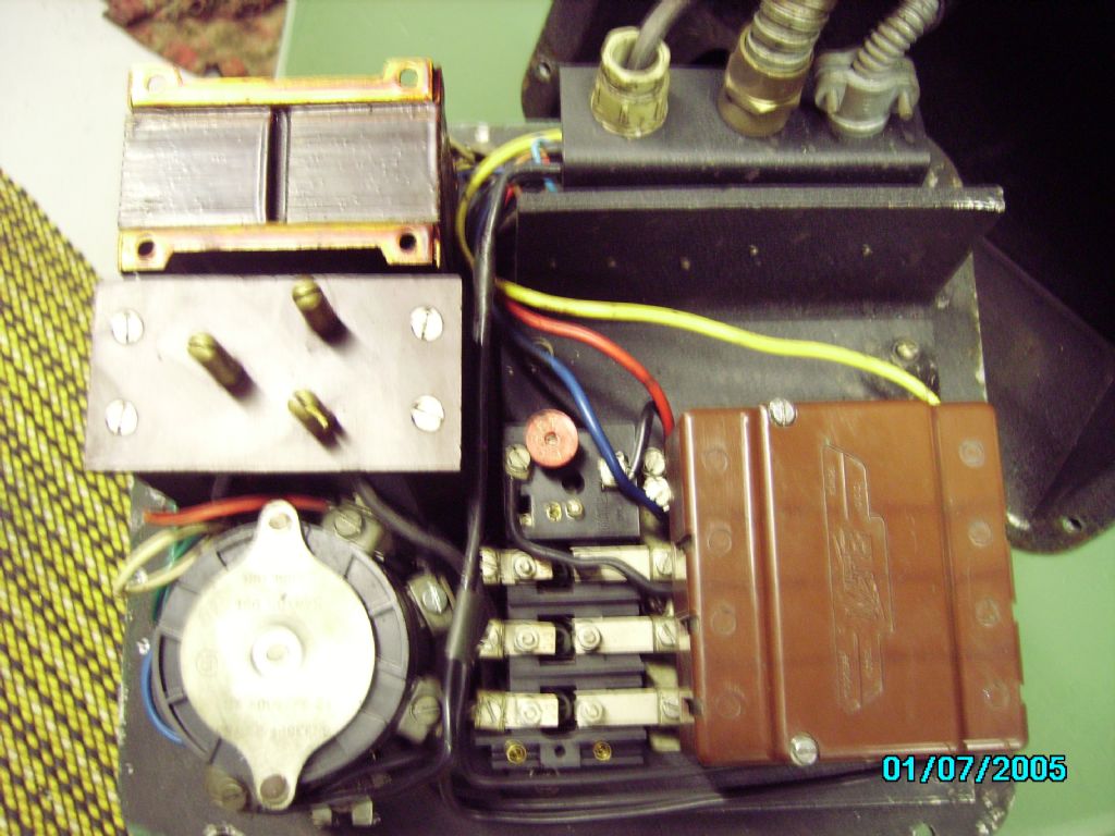
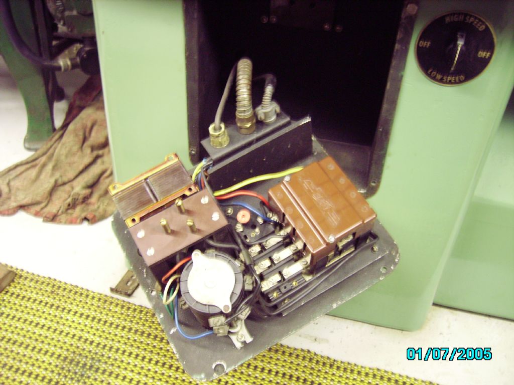
I am getting it wrong too! you lift the front lever to turn the lathe motor on, and push it down for off! I spotted this today when I used my lathe, you can't miss it really!. OK, time to drain the coolant sump unblock the pump, and see if it is actually running, or just buzzing. If it is actually running, we know that three phases are coming out of the converter.I think there is an exposed peice of pump shaft that you can see rotating, I will check tomorrow.. Here is the starting sequence, turn on the power, set the motor/coolant pump switch to motor, and lift the front lever with the red control knob, when you lift the lever, you should hear the contactor pull in, and the motor should run. When you lift the lever, it operates the "limit" switch at the rear of the headstock which completes the circuit to the coil in the contactor, and the contactor pulls in, and the motor should start. if the fwd/rev switch is after the contactor (I suspect it is) then it may be that this switch is faulty. I assume you have tried switching between forward and reverse a few times, but if you haven't, do it with the power off, then try the lathe again. can you post up a pic of the contactor taken from square in front of it so we can see all the contacts and connections (several pics not objected to!), and also a general one of the headstock controls, and the motor panel, so we can see what we are dealing with. We will get to the bottom of this! In that case i definitely do not hear the contactor, the only noise i hear is the slight click of the red or in my case black knobbed handle clicking into place. Can't get any more pictures of the lathe till the 13th, but i think i may have a few other pictures somewhere
Thats the isolator box i had to wire a plug to when I first received the lathe, not too relevant I don't think, but just covering all bases, as there could be issues anywhere
And that's how i wired it, I think it was 2.5mm 4 core. So as you said that should be earthed?
Looking closer at the motor plate it says its from 1955, so quite old. It also says if i read it properly that the motor is 1.5hp. perhaps the earlier models had smaller motors. I will double check this when i'm home as the picture isn't the best. However, if it is 1.5hp then perhaps a 3.5hp static converter will be enough to power it for now (especially if Mal said his powered it for a few years)
This is where the wires leave the control board and lead through the casing to the coolant pump, just the 3 white wires
Another random picture, doubt it's of any use, but the more the better
Was this the sort of straight on picture you wanted?
That's the lathe itself, still has a lot of cleaning to be done, but need it working first. As you can see, my forward reverse switch is not original like on your lathe Phil. I'll be able to get more pictures and even videos when i'm back Edited By Richard Kirkman 1 on 27/11/2019 20:07:49 |
| 27/11/2019 12:03:24 |
Posted by SillyOldDuffer on 27/11/2019 11:37:46:
Contactors are electrically operated switches. Basically a low safe voltage is applied to a magnet coil that pulls the switch contacts together, and they do all the heavy lifting. Your contactor is very old-fashioned; everything is out in the open, making it vulnerable to damp and dirt.
Joining the dots:
Although the contactor may be of obsolete design, the control circuit is isn't! Much the same is used on modern lathe.
Modern contactors like the example above come in nice sealed boxes, rather smaller than yours, with no maintenance required. Entirely possible to replace the old contactor with a new one, the main problem being to identify one with a 240V operating coil, and six switches. They're readily available. (Ignore the annotations - they're for a single-phase motor.) Dave Dave, I don't think the pump does actually run. I just hear it buzzing, but I don't think it's a loud enough buzz for the motor to be running. But the point is it's getting some electricity
When I turn the on switch, I hear a large clunk noise. But I think that's just the noise that the switch makes. I don't think the contactor has moved apart from when I'm in there. The tongue you mentioned is definitely missing, I hadn't noticed before. And I've only just noticed now, that another tab and contact that should be paired(the one that's broken in the bottom of the case) should probably go here?
The white/dirty white cable going from the bottom is the coolant pumps cable. So the blue wire has been put down there when it should be going onto the contactor above and have the tab which is loose in the bottom connecting the pump. Does that make sense to you? I'm just guessing sti, but it seems to be logical to me |
| 26/11/2019 20:03:27 |
Posted by Phil Whitley on 26/11/2019 18:23:24:
Hi Richard, mine is definitely a Mk1, but looking at the levers on yours I would say it is a very early mk 1, I do not have the "safety apron". If you can hear the contactor pull in when you press the front lever down, and the switch for the main motor is set to on, then it should run, stupid suggestion, the chuck guard doesnt have a safety switch on it? The main contactor is pulling in, and usually the safety switches are wired into the coil circuit, but who knows if a second contactor has been added. Turn OFF and disconnect the power, and with a multimeter, see if you can test from the contactor to the reversing switch, and from the reversing switch to the motor. This does depend on whether the reversing switch is before the contactor or after it, but I suspect it is after, it is a start anyway! Phil
I'm getting quite confused with all these terms. Specifically which part is the contactor, is it this part? And if its not this part, what is this part and what does it do and why? Or is it this part at the back. The piece that says limit switch has a pin that moves up and down when i switch the lathe on from the lever on the front and makes a click as it goes into place. But, I'm not too sure what noises i'm looking for? And no, there isn't a switch on the chuck guard. Also, i have access to the motor round the back so I am able to check if it buzzes but i have not done so yet. Thanks Edited By Richard Kirkman 1 on 26/11/2019 20:04:37 |
| 26/11/2019 17:02:47 |
Posted by mal webber on 25/11/2019 19:55:39:
HI, I have a mk1 1/2 student run by a pc 60 and sometimes not often it trips like a overload switch behind the front panel on the lathe side, I will take a picture if you like, but like has been said make sure all guards are in place first has they have safety switches . P.S I did use the pc 40 with my student for about 4 yrs it done the job for the first year and then decreased in power after that i.e would not run higher speeds but would still run lower ones, up in till the point the chuck needed a bit of help to start and if it did not start straight away the trip switch would trip out on the lathe. Edited By mal webber on 25/11/2019 20:07:14 Mal, how did you initially get your student to work? Was it just plug and play for you with your pc40 or did you have any issues? |
| 25/11/2019 21:12:10 |
Right, Thanks for all the responses so far, I have A LOT to look at. If anything I do enjoy this as I like learning about machines, as long as i can get it working. Dave-Thanks for your response- the fuses are probably fine, although i haven't taken anything to pieces in there so i'll check that when i'm back. The lathe has a No Volt Release built in as far as i know? but it has no safety parts like an emergency stop button. The main off/on/on with coolant pump switch provides a very large satisfying clunk but I am unsure if that's the same thing as the contactors you're on about as i haven't been brave enough to turn it on without the cover on, not that that would help as of the 3 pins that need to be plugged in. I don't understand what some of the components in there even do like this entire part in the picture below
But in this part it looks like the contacts are very rusted, if they are contacts that is. As far as the light switch not being there, I would like to fit one, but I cant seem to find a genuine replacement for the part(any direction from anyone appreciated?) Ideally i'd like to understand every part in here just so i know what's going on. Someone has definitely been in here before me as when i first took the cover off I found this drawing
Phil- I see you're in Driffield, I'm at University in Hull, but the lathe resides at home in Darlington. I haven't looked at the key in the end of the lathe, however the cupboard doors do open, so I presume its on. I think your lathe might be the mk1.5 as it looks like it has the reverse forward switch on the back of the lathe, where as mine was added 3rd party ( I think, definitely doesn't look official). Apart from that, the inside of the components in the lathe should be the same when it comes to the electronics. The contactor makes a nice clunk noise when i activate the lever And yes I do have the manual specifically for the earlier model and this is the wiring diagram from it Clive and Andrew- Yes it most likely is a static converter then, not rotary (It's also not making any noise so definitely not rotary). Perhaps a short term solution if I can upgrade. The motor plate says its 2.5hp so would a static 3.5hp converter possibly manage? If not, i may have access to a proper rotary one if i beg
Mal-So your pc40 worked with your mk1.5 for a while. My mk1 has a 2.5hp motor and as far as i'm aware, the mk1.5 had a 3hp motor. So maybe the pc40 will work a bit better for mine (still short term fix)? Simon- Yep thats all gobbledegook, however i'll try my best. As andrew says, yes there are 3 live wires and earth, so no neutral. The converter is definitely 3 phase, but as Andrew also said, its not true three phase. According to the converter, its applying 0 amps, but it says that it has power from 230v mains so 415v should be coming out, I don't think the lathe is drawing anything from it though. Thanks, I'll try not to electrocute myself. Thank you everyone for your comments so far, I still cannot check anything till the 13th December but this'll hopefully help me with some understanding of what's going on before I attempt anything
|
| 25/11/2019 13:37:59 |
Afternoon, First post on here so here we go In the summer I purchased a Mark 1 Colchester student completely unseen and untested (forgive me) the man said it was working fine although i'm unsure how long its sat around for. I spent a while cleaning it up and getting ready to start it as it looks like it hadn't been used for many years. I had to fit a new fuse box to the garage and a 32 amp socket so the rotary converter would work. I'm using a Clarke pc40 3.5hp rotary phase converter to power the lathe. The lathe is 3hp I had to stop as i moved back to university for a few months, but I have had a day or two now to play with it while i'm home So, i have done some work on the lathe, replacing a sliding sleeve in the headstock so now i believe it is mechanically functional. I didn't want to switch it on without replacing this part as I thought it could have done more damage. So, going plugging everything in, its all looking fine, I switch the motor on and nothing happens, just nothing. When I switch the lathe to on with coolant pump, the coolant pump makes noise as if it is working (but i have yet to clean out the tank and fill it, so i don't know if its pumping or just making noise) I have taken off the front cover to look for issues but i am definitely no electrician, i have no idea what i'm looking at. I have the wiring diagram, but i have no idea what to look at and then how to test for issues. The rotary phase converter has a current reading on it so you can see how much it is pulling, even with the coolant pump on, it remains at zero. Does anyone have an idea of where to start? I understand which wires are which and where they're going to, but not the things they're going into. there is a loose piece pictured in the casing that looks broken and i have no idea where it may have gone. The reverse forward switch which has been added looks fine to me and all the pieces inside the case are fine. I still have yet to clean around the back of the lathe, but it will clean up to the same as the rest of the lathe, just very thick grime I have taken plenty of pictures, but i will be unable to access the lathe again till the 13th December as I have to go back to University. Not too sure how the photos work on this, so i'l attach a link to the album. If people can't view that then i'll post them normally https://photos.app.goo.gl/eWFpzzp7p7Wasart9
Thanks |


Magazine Locator
Want the latest issue of Model Engineer or Model Engineers' Workshop? Use our magazine locator links to find your nearest stockist!
Sign up to our Newsletter
Sign up to our newsletter and get a free digital issue.
You can unsubscribe at anytime. View our privacy policy at www.mortons.co.uk/privacy
Latest Forum Posts
- *Oct 2023: FORUM MIGRATION TIMELINE*
05/10/2023 07:57:11 - Making ER11 collet chuck
05/10/2023 07:56:24 - What did you do today? 2023
05/10/2023 07:25:01 - Orrery
05/10/2023 06:00:41 - Wera hand-tools
05/10/2023 05:47:07 - New member
05/10/2023 04:40:11 - Problems with external pot on at1 vfd
05/10/2023 00:06:32 - Drain plug
04/10/2023 23:36:17 - digi phase converter for 10 machines.....
04/10/2023 23:13:48 - Winter Storage Of Locomotives
04/10/2023 21:02:11 - More Latest Posts...
- View All Topics
Support Our Partners


Shopping Partners
Subscription Offer

Latest "For Sale" Ads
- Reeves** - Rebuilt Royal Scot by Martin Evans
by John Broughton
£300.00 - BRITANNIA 5" GAUGE James Perrier
by Jon Seabright 1
£2,500.00 - Drill Grinder - for restoration
by Nigel Graham 2
£0.00 - WARCO WM18 MILLING MACHINE
by Alex Chudley
£1,200.00 - MYFORD SUPER 7 LATHE
by Alex Chudley
£2,000.00 - More "For Sale" Ads...
Latest "Wanted" Ads
- D1-3 backplate
by Michael Horley
Price Not Specified - fixed steady for a Colchester bantam mark1 800
by George Jervis
Price Not Specified - lbsc pansy
by JACK SIDEBOTHAM
Price Not Specified - Pratt Burnerd multifit chuck key.
by Tim Riome
Price Not Specified - BANDSAW BLADE WELDER
by HUGH
Price Not Specified - More "Wanted" Ads...
Get In Touch!
Do you want to contact the Model Engineer and Model Engineers' Workshop team?
You can contact us by phone, mail or email about the magazines including becoming a contributor, submitting reader's letters or making queries about articles. You can also get in touch about this website, advertising or other general issues.
Click THIS LINK for full contact details.
For subscription issues please see THIS LINK.
Digital Back Issues


Donate

 Register
 Log-in
Model Engineer Magazine
- Percival Marshall
- M.E. History
- LittleLEC
- M.E. Clock

ME Workshop
- An Adcock
- & Shipley
- Horizontal
- Mill

Subscribe Now
- Great savings
- Delivered to your door

Pre-order your copy!
- Delivered to your doorstep!
- Free UK delivery!