Member postings for John Munroe
Here is a list of all the postings John Munroe has made in our forums. Click on a thread name to jump to the thread.
| Thread: Avoiding jams in telescopic tracks |
| 11/02/2016 13:48:15 |
Hi John, I've thought about a blind type base, but I worry about wear and tear as the base would need to be rather thin to keep the small package. These are actually parts of two parts that are separated by a spring. The spring is compressed when the two parts are pressed together. Inside the chutes, there can be arbitrarily positioned blocks. I wonder if the jamming issue could be resolved by giving the chutes a better finish, e.g., 1.6Ra? Perhaps, the gaps between the two could be reduced? Would it be reasonable to make the gaps 0.05MM on each side (so that lubricant won't get squeezed out)?
Thanks John |
| 10/02/2016 19:48:18 |
Posted by pgk pgk on 10/02/2016 19:25:52:
can you simply reverse the system and have the wide end as the discharge end..any 'jams' hopefuly being discharged on withdrawal. Or if you don't need access to the top of the shute then a sprial with a flexible inner sheath? Or is it acceptable to have an upward or downward folding hinge midway? Unfortunately both ends are supposed to be used for discharged. The setup is rather small, so I think hinges will fit in there. I'm not sure if I completely understand, but how does a spiral work here? Thanks
|
| 10/02/2016 19:10:40 |
Hello I'm trying to design a small metal telescopic track (6cm x 2cm when extended) where small objects may be arbitrarily positioned inside. Here's an example:
In the above example, the green block jams the tracks as the bottom cannot move upward. Does anyone know of a better design such that the tracks won't be jammed? I've thought about putting a sleeve on the inside, but if it was 6cm long and covers the entire extended length, it'd overhang when retracted. Any help will be appreciated. Thanks |
| Thread: Orbit modelling: Earth-Moon Like |
| 06/02/2016 14:01:54 |
Posted by Neil Wyatt on 06/02/2016 13:46:45:
The moon actually 'librates' and so the exact spot facing the earth changes slightly, you could say ant small errors in you device carefully model this extra motion
Yeah, I'm aware of that. I'm having problem with even just connecting the two discs together! |
| 06/02/2016 09:52:43 |
|
Sure, I know orreries. However, I just wonder if there's a simpler way to achieve something similar in a more compact housing if the two discs can be directly joined up. I'm only trying to model the motion of the objects on one plane, so there doesn't need to be empty space between the discs. Also, I'm not sure traditional orreries can dynamically adapt/self-adjust to objects shifting axis. Thanks John Edited By John Munroe on 06/02/2016 09:54:12 Edited By John Munroe on 06/02/2016 09:56:05 Edited By John Munroe on 06/02/2016 09:56:21 |
| 06/02/2016 09:11:57 |
Hello I'm hoping to make a small mechanical demo (~10cm tall) that models an orbit that is similar to the Earth-Moon orbit - that is, only one side of the Moon faces Earth. I'm hoping to keep it simple, so here's my idea so far
where the blue and yellow represent Earth and Moon, respectively. These are meant to represent a different planet and its moon though. The orbit of the Planet (blue) and its Moon (yellow) has the following differences: - Planet is eccentric My question is: how should the two discs be connected in order to to have the above properties? I've thought about using springs, but I think it'd be quite flimsy. Thank you for the help in advance! |
| Thread: Fitting rods/shafts in plastic gears |
| 31/01/2016 11:40:42 |
Posted by Ian S C on 31/01/2016 10:44:06: John, how about a 6 mm dia bush, with a 3 mm hole. Don't know if Loctite works on plastic, but the outside of the bush could be lightly knurled with a fine straight knurl, a hole drilled through and tapped a suitable size. That's how this 3 mm shaft is fitted in a 5 mm bore bearing on my smallest hot air engine. Ian S C That's interesting! Have you got pictures of the knurled bushings used? Did you make them or buy them off the shelf? I guess you used Loctite on yours - right?
Thanks |
| 31/01/2016 09:50:10 |
Thank you for all the input. I have a related question: the shaft of my motor is actually just 3MM in diameter. Given that the gear bores are 6MM in diameter, what's a good way to fit the 3MM shaft in a 6MM bore? I'm hoping to avoid using a shaft coupler. Could I add a metal ring of some sort inside the bore such that the resulting bore diameter will be reduced to 3MM?
|
| Thread: Offset bevel gears installation? |
| 31/01/2016 08:52:21 |
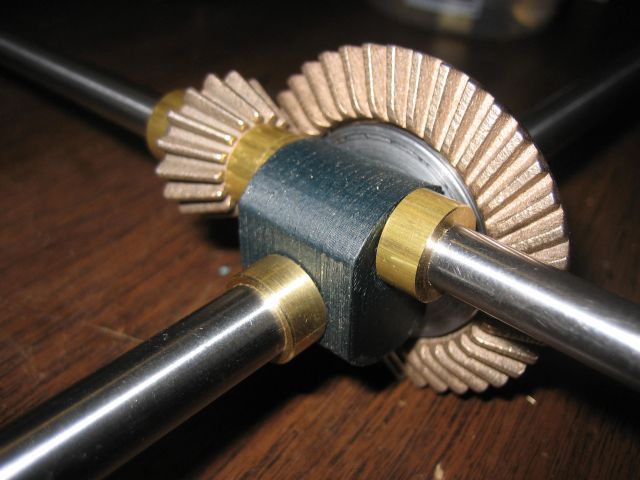
Hello I'm looking at some bevel gear setups, e.g.,
and
To me, the rods seem to be offset such that they don't intersect each other. However, aren't bevel gears supposed to mesh along the centre axes? Thanks |
| Thread: Fitting rods/shafts in plastic gears |
| 31/01/2016 06:41:59 |
Hello everyone, what a wonderful forum this is! (Long time lurker...) |


Magazine Locator
Want the latest issue of Model Engineer or Model Engineers' Workshop? Use our magazine locator links to find your nearest stockist!
Sign up to our Newsletter
Sign up to our newsletter and get a free digital issue.
You can unsubscribe at anytime. View our privacy policy at www.mortons.co.uk/privacy
Latest Forum Posts
- hemingway ball turner
04/07/2025 14:40:26 - *Oct 2023: FORUM MIGRATION TIMELINE*
05/10/2023 07:57:11 - Making ER11 collet chuck
05/10/2023 07:56:24 - What did you do today? 2023
05/10/2023 07:25:01 - Orrery
05/10/2023 06:00:41 - Wera hand-tools
05/10/2023 05:47:07 - New member
05/10/2023 04:40:11 - Problems with external pot on at1 vfd
05/10/2023 00:06:32 - Drain plug
04/10/2023 23:36:17 - digi phase converter for 10 machines.....
04/10/2023 23:13:48 - More Latest Posts...
- View All Topics
Support Our Partners


Shopping Partners
Subscription Offer

Latest "For Sale" Ads
- Reeves** - Rebuilt Royal Scot by Martin Evans
by John Broughton
£300.00 - BRITANNIA 5" GAUGE James Perrier
by Jon Seabright 1
£2,500.00 - Drill Grinder - for restoration
by Nigel Graham 2
£0.00 - WARCO WM18 MILLING MACHINE
by Alex Chudley
£1,200.00 - MYFORD SUPER 7 LATHE
by Alex Chudley
£2,000.00 - More "For Sale" Ads...
Latest "Wanted" Ads
- D1-3 backplate
by Michael Horley
Price Not Specified - fixed steady for a Colchester bantam mark1 800
by George Jervis
Price Not Specified - lbsc pansy
by JACK SIDEBOTHAM
Price Not Specified - Pratt Burnerd multifit chuck key.
by Tim Riome
Price Not Specified - BANDSAW BLADE WELDER
by HUGH
Price Not Specified - More "Wanted" Ads...
Get In Touch!
Do you want to contact the Model Engineer and Model Engineers' Workshop team?
You can contact us by phone, mail or email about the magazines including becoming a contributor, submitting reader's letters or making queries about articles. You can also get in touch about this website, advertising or other general issues.
Click THIS LINK for full contact details.
For subscription issues please see THIS LINK.
Digital Back Issues


Donate

 Register
 Log-in
Model Engineer Magazine
- Percival Marshall
- M.E. History
- LittleLEC
- M.E. Clock

ME Workshop
- An Adcock
- & Shipley
- Horizontal
- Mill

Subscribe Now
- Great savings
- Delivered to your door

Pre-order your copy!
- Delivered to your doorstep!
- Free UK delivery!