Member postings for SillyOldDuffer
Here is a list of all the postings SillyOldDuffer has made in our forums. Click on a thread name to jump to the thread.
| Thread: Gidday :) |
| 05/07/2023 20:09:35 |
Welcome Red Duck! Please let us know how you get on - what other people do with their machines is always fascinating. Some bad news you'll gave to break gently to your wife though. Now you've caught the bug and bought a mill, it's vital to buy a lathe as well. Urgently. And then many, many other
Dave |
| Thread: CROBALT...Lathe tools |
| 05/07/2023 19:59:50 |
This is what their website says: Crobalt® – An Ideal Cutting Tool For Wood-Working Ideal Wood-Working Material :: Crobalt® with its inherent resistance to abrasion, corrosion, and certain acids is an ideal alloy for tools used in the woodworking industry. Crobalt’s characteristic ability to accept a keen edge makes it ideal for woodworking where work piece surface finish is critical; however, Crobalt®is not as brittle as some other cutting tool materials thereby making it less susceptible to cutting edge flaking. Additionally, Crobalt®, by virtue of its high red hardness, will retain its strength at the elevated temperatures sometimes found in woodworking operations. Crobalt®is not recommended for the maching or cutting of plywood or other composite wood materials. That's OK because HSS is often used to make woodworking tools, and a variety of HSS that resists organic acids is advantageous, doubly so if it also takes a good edge. An HSS that takes a good edge is also likely to work well on the less rigid, slow, and not so powerful lathes typical of Model Engineering workshops. Our machines have virtues other than metal-munching. Be quite interesting for a group of Myford owners to compare the performance of:
Which produces the best finish, which removes metal fastest, which has the lowest resharpening down time, and which is the most affordable? I doubt there's an outright winner because they have different pros and cons. The type you want is the one that works best in your workshop that you can afford. Maybe we're all a bit behind the times, HSS and Tungsten Carbide are so last century! Anyone tried Ceramic, Boron Nitride, Carbon Nitride, or Diamond inserts? Dave
|
| Thread: Lathe/VFD/DRO issue |
| 05/07/2023 11:52:50 |
Posted by Emgee on 04/07/2023 20:09:50:
Posted by SillyOldDuffer on 04/07/2023 17:47:31: . Single phase has two wires, both of which would be 'hot', except one is earthed by the supplier at the transformer. Thus homes get two wires, Line (or Live), and Neutral. Although Neutral carries current, it's safe because it and anyone likely to touch it are all at earth potential. Also, each house has it's own separate earth (details vary). The house earth protects against failure of the supplier earth and also allows anything in the building that might accidentally become hot to be grounded. So if a bare Live wire accidentally touches a hot-water pipe, fuses blow rather than allow the plumbing to become shock hazard. House earths are designed and implemented in a particular way, affordably fit for purpose, but not suitable for everything. Dave I believe some points in your statement need more discussion. The neutral conductor cannot be termed safe as if the neutral conductor is broken between the load of a piece of equipment on the circuit and the consumer unit it will be capable of giving a full mains voltage shock to a person or animal if they provide an earth path for the voltage to travel down. Many properties rely entirely on the suppliers earth (PME) and have no independent earthing arrangement, it is only in mainly rural areas where no supplier earth is provided where the installation will be provided with it's own earthing system, usually copper rod/s depending on soil resistance. Emgee Agreed - I was trying to keep the example simple! I hinted it was more complicated, by saying 'Also, each house has it's own separate earth (details vary).' Here's an example in which an 'Extraneous-conductive-part' is connected, often not present. But note the 'PEN Conductor' is earthed by the supplier at the transformer, and also along the cable. One of these earths is likely to be nearish to the house. The Neutral wire is 'safe' because it cannot normally be above ground potential. Perhaps 'safer' is more accurate than 'safe' because there are faults that cause 'Neutral' to become 'hot'.
My main point though is that a mains safety earth is very unlikely in any configuration to be a good radio earth. The wires are too long. Dave |
| Thread: DTI travel. |
| 05/07/2023 10:57:12 |
Posted by Bill Davies 2 on 04/07/2023 17:09:09:
.... As an inspector, I used long travel plunger type dial clocks for checking tooth size on gear shaper cutters. The lever-types were used for comparing close to the zero reading. ...Bill I'm hungry for more on how Inspectors work please Bill. I know a bit about practical home measurement and fitting, and have an interest in Metrology, but there's much I don't know about the how, what, why, and when of inspection. I'm sure there's more to it than haphazardly poking stuff with a GO/NO-GO gauge. Might make a good MEW article - Neil's looking for new material. For example, within tolerances, even a simple hole has to be made in the right place, with the correct diameter, and depth, straight, circular from end-to-end, and with a given surface finish. In my workshop, drilling is often imperfect, with holes off-centre, not perfectly round, veering off axis, tapered, depth off, and scratched. Mostly doesn't matter because what I do rarely needs better than about 0.05mm. How would an Inspector check a Duffer built part, say 7 off 5mm holes drilled 10mm deep on an accurately centred 100mm diameter PCD, all dimensions within ±0.005mm? Dave
|
| Thread: Workshop Clock |
| 05/07/2023 10:09:57 |
A few clues. The clocks are:
Unknown:
Are the batteries the correct type, not too cheap or fakes, and in date? Could Iain's batteries all be from the same ancient package, perhaps stored badly in his workshop? The ideal battery is an old-fashioned 1.5V Leclanche because their chemistry favours intermittent low power operation like clocks and doorbells. Hard to find these days because most battery powered devices need more power, usually in applications where batteries aren't expected to last for years. Ubiquitous when I was a boy and they always leaked! Some modern types are prone to self-discharge, especially rechargeables. Too cheap batteries usually contain fewer active chemicals and/or the chemicals are a little impure. As a result they don't last well. The 'free' battery that comes with a new item is often weedy, maybe to keep costs down, or because its chemistry has been optimised for long storage rather than energy content. As clocks and doorbells are a tiny proportion of the battery market, we're more or less forced to buy unsuitable batteries for them. Dangerous to generalise, but for clocks I avoid 1.2V types and go-faster variants. For example, Duracell sell Optimum, Plus, and Simple ranges, where Plus and Optimum deliver 100% and 200% more energy than Simple, making them suitable for power hungry motors etc. Clocks do not need more energy, so there's a reasonable chance 'Simple' is a better choice, not only cheaper, but potentially longer running. Two ways of thinking about workshop clocks. One is to buy cheap because the unfriendly environment is likely to kill them, so treat the clock as a consumable. The other is to buy a well made clock in hope it's innards will be better protected against condensation, swarf and conductive dust. My suggestion is to protect the clock or a bought movement with by enclosing it in a home-made box (wood and Acyrlic), and to power it with a bigger battery, a C or D rather than an AA. I'd solder the battery directly to the clock with a flying lead, but holders are available:
Maybe insulate the battery as well by wrapping it in some towelling or a polystyrene box. I wear a wrist-watch! Dave |
| Thread: Lathe/VFD/DRO issue |
| 04/07/2023 17:47:31 |
Posted by Rockingdodge on 03/07/2023 17:33:45:
...
The one thing that confuses me is the difference between the safety earth and shielding earth ... then surely earth is earth and thus the mains cable carries the difinitive earth? Earthing is complicated and done for different reasons.
EMC is yet another case, albeit closer to the radio example than the others. EMC uses shielding to stop inductive, capacitive, and electromagnetic coupling. As the coupling is usually electrically unbalanced, shielding won't be effective unless it too is earthed. And because shielding often consists of bare metal, it's necessary to ground it for electrical safety reasons. Unfortunately electrical safety earths are rarely good Radio earths. One problem is the earth wire on the lathe connects through a longish lead to a power socket. Then the supply earth wire runs around the building until it reaches the Consumer Unit, probably tens of metres away. From there, it's connected to the supply earth, probably some distance away. To a high frequency wave, all this wire looks more like an antenna or transmission system than an earth. It becomes a good way of transferring EMC further, not a way of stopping it. And when it gets to the actual safety earth, perhaps just a few feet of copper rod banged into the ground, 1ohm at 50Hz can behave like thousands of ohms at Radio Frequency. Ideally, there should be an EMC earth near the VFD. However, as this could be difficult, expensive, or break electrical safety rules, it's usual to use the electrical safety earth and hope it will do. The safety earth may need help! I see Robert supplied a Ferrite: I have no experience with these and VFD interference, but in principle they 'choke' wires, making it hard for EMC to get further whilst having no effect on normal function. Not as effective as a properly designed filter, but might be good enough, especially in conjunction with other measures, In that vein, experiment with earth points on the machine. Sometimes adding another earth point will successfully short out the EMC. In other cases, a new earth point creates a loop that makes it worse. Finding the best combination can be hard work, and maybe there isn't one. Professionals approach the problem rather differently. When money is no object, EMC is conquered simply by following best practice from end to end. Everything is comprehensively shielded and filtered to stop electrical muck getting in or out. Not cheap...
Dave
|
| Thread: Poor surface surface finish milling steel |
| 04/07/2023 15:28:29 |
I avoid machining Stainless because most of them work-harden. By no means impossible, but expect trouble. Here's what the British Stainless Steel Association say, my bold: When machining stainless steels it important to ensure that there is no dwell or rubbing caused by machine vibration or tool chatter. Machines must be ‘substantial’ and capable of making the deep cuts needed in machining austenitic stainless steel without slowing down the set feed or surface speeds. Small training or ‘hobbies’ lathes and milling machines intended for machining mild steel, brasses etc. are unlikely to be substantial enough for the successful machining of stainless steels. By 'successful machining' they mean reliably cutting metal to size and finish commercially without needing a skilled operator to experiment for best results. All will be well using a rigid powerful machine fitted with the right type of cutter, spinning at the correct RPM, with a suitable Depth-of-Cut and steady Feed Rate, suitable lubrication/cooling, and a way keeping swarf out of the cutting area. Of 316 Alco say: 316 stainless steel has good machinability. Machining can be enhanced using the following rules:
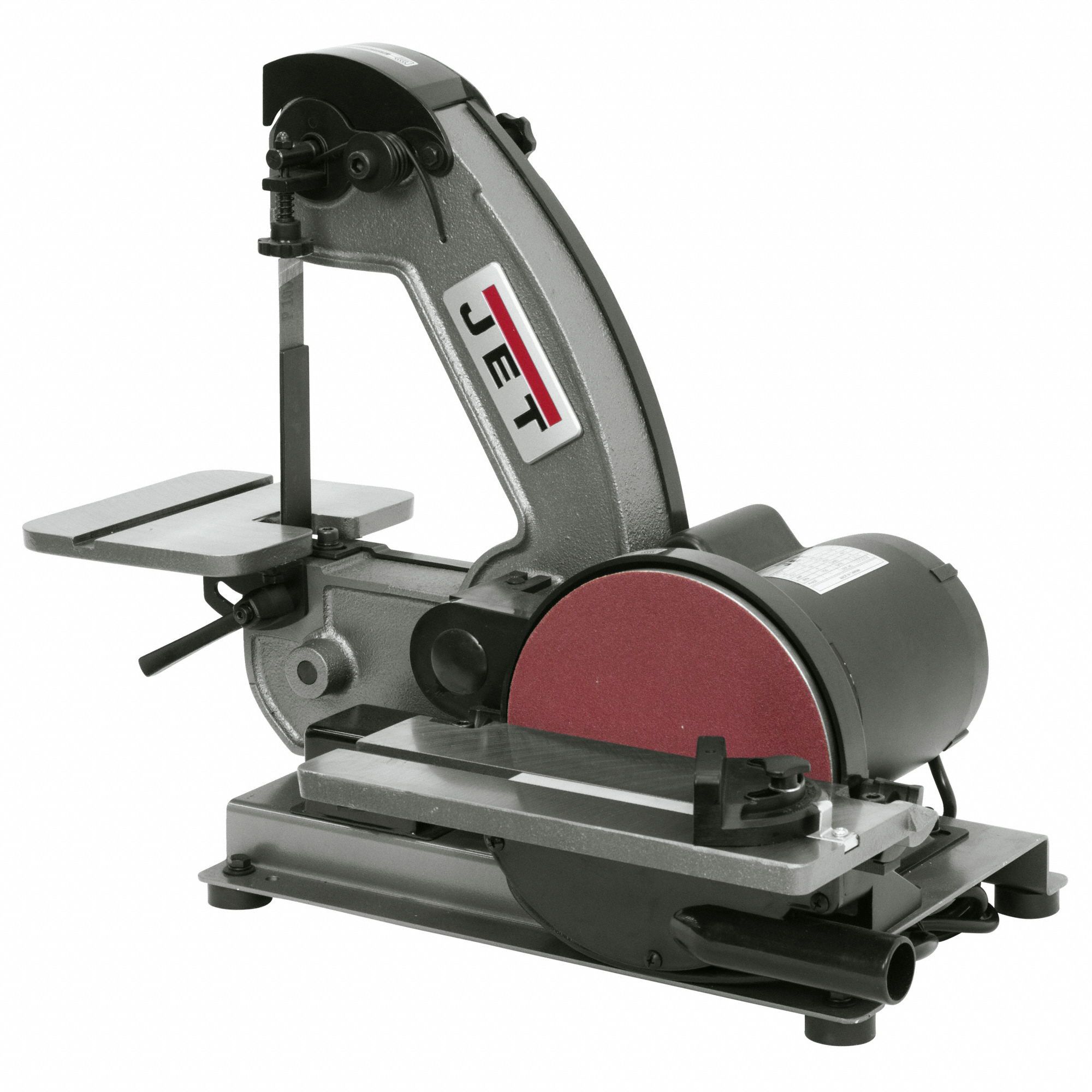
So the odds are stacked against small workshops. My WM18 does what I want, but it's not particularly rigid, or powerful, I only own a limited range of cutters, they're not all in good condition, my experience of stainless is limited, and I'm not a naturally talented machinist. Whilst I and the machine cut machinable alloys reliably well, I'm not surprised when any of the many difficult Alloys turns out to be a challenge. I avoid scrap unless I know what it is. SD's photos show, I think, the result of work-hardening. Rather than cutting, the cutter is rubbing and bouncing along the surface. Rubbing hardens the surface so effectively that HSS struggles to penetrate and is rapidly blunted, the end. All is not lost! The finish can be improved by using an inexpensive Belt Sander like this example as a Linisher: Not sure what others find, but in my workshop milling and lathe cut surfaces often benefit from a mild abrasive touch-up. Depends on the material, but ordinary mild-steel usually gets a licking because it's a bit smeary. Leaded mild-steel, 6082 Ali and Brass are more likely to come clean off the machine. Dave
|
| Thread: Lathe/VFD/DRO issue |
| 03/07/2023 14:45:37 |
Posted by Rockingdodge on 03/07/2023 13:32:24:
Now that I will have the necessary bits to 'hopefully' remove the interference from my vfd/motor/mains in cabling I just have a couple of queries:- Is it bad practise for the mains in and the vfd to motor cable to cross over or should I route the cables away from each other? Can I tie all the earths onto the mounting plate of the enclosure and then take one into the vfd? So the final question is - do I earth the screen earth both ends or not? Regards Roger Keeping cables apart helps. Try to run them so they're not parallel. If they have to cross do it at a right angle. Earthing - try both. I'd start by earthing the VFD to the mounting plate, and if that doesn't work try earthing it separately. Which end to earth, or both is much debated. The only printed advice I've seen was for double shielded wire, which suggested the inner be earthed at the noisy end, and the outer at both ends. I'd start by earthing only at the VFD end, and if that didn't fix the problem, both ends. Note that an earthed shield shouldn't be used as a safety earth. The safety earth has it's own wire, preferably inside the shield. The cure is uncertain because EMC travels by 3 different mechanisms and what needs to be done varies by frequency. A Radio Engineering problem, Electrical, and the way wires behave when high-frequency power is applied to them is counter-intuitive and unpredictable. So expect to try different combinations. If Robert RPI reads this, would Ferrites help? My feeling is not. Dave |
| Thread: Professional Machine Fettling |
| 02/07/2023 15:39:00 |
Posted by Dr_GMJN on 02/07/2023 14:08:44:
Posted by Bill Phinn on 02/07/2023 13:44:00:
Dr G, it might be a good idea at this stage if you removed the offending gib strip and had a close look at it and the channel it sits in. I appreciate the advice, but I give up with the thing. It’s never been great even at side milling mild steel, and the z-axis control seems flawed in terms of backlash. In fact this morning while working on a steam engine part, the cutter dragged into my milling vice and took a chunk out of it. The axis was locked, but obviously not tight enough. The vibration of side milling probably loosened it. Whatever the cause (my fault or the machine) I’m ready to give it up as a dead loss at this point. The other odd thing about it is that to get the z-axis central over the x-y table, the table has to be extended so it’s significantly overhanging the guides. Presumably this doesn’t help with stiffness, and has the knock-on effect that my milling vice also overhangs the x-axis, partially obscuring the y-axis locking lever (that I fitted myself). Only a lost cause when the owner surrenders! Taking a break is allowed but Model Engineers never give in. The faults that frustrate me most are those that have me going round in circles. This could be an example.
Unfortunately it's rather easy to get things wrong when fixing machine tools - they appear simple but have hidden depths. Issues are easier to diagnose when one has a dollop of experience. In the absence of experience, assume nothing and ask the forum! Photos plus full lists of all faults and what's already been done to the machine would help. I empathise. I'd much rather make things than waste time fixing tools. Dave |
| Thread: windows file explorer question |
| 01/07/2023 20:17:50 |
Posted by gerry madden on 01/07/2023 16:35:32:
Thanks all for taking time to comment but as SOD put it, its still as clear as mud, at least to me ! In the most recent occasion that this issue occurred (that prompted me to make this post) it was with a pdf. I think, everything I read refers to word documents. None of the '3 files' is ever readable to me so I cant work back and work out what caused this to occur. There must be some special conditions at play as this isn't the norm when I save files. Let me see if I can find the conditions that reproduce the fault and I will come back for more help. Gerry I think what's happening is Windows has lost the file association. When a file is opened with Explorer, the file extension is used to identify whatever program will work with it. So if the extension is .TXT, Explorer usually launches Notepad. As almost every computer is set up differently, File Associations can be added, changed and removed. Normally by installers, also manually. Several ways File Associations can be lost. Installing and uninstalling applications, malware, malfunction or owner messing with the Registry, and even Alpha Particles! If Explorer doesn't have an association, it may default to a general purpose action such as 'show what's inside' rather than the expected 'launch the application'. Sounds like your problem. Explorer doesn't know what to launch, but its smart enough to name what's inside. In Explorer, try Right-Clicking on the file. Should get a menu with an Open option that lists Applications, one of which can be selected manually. For example, if the file is a PDF, a PDF reader such as Adobe, Foxit, Word, OpenOffice etc. Look for the name of the application that created the file in the first place. To restore automatic recognition : How to set a File Association. Dave |
| Thread: Is this a scam? |
| 01/07/2023 19:37:18 |
Posted by Peter Greene 🇨🇦 on 01/07/2023 17:32:41:
What do you think of this: Your $20.00 Undocumented Claim in the Canadian Optical Disc Drives class action is approved. ... Strong smell of fish, even on this side of the Atlantic! Unlikely in the UK for anyone to be sent money out of the blue in this way. When companies are fined here after breaking the law, the government gets the money. Individuals seeking damages have to go through the courts. There are no Fairy Godmothers showering victims of crime with money! May be different in Canada. Why not ask Competition Bureau Canada for their advice? They cover Fraud and Scams! Dave
|
| Thread: Sensitive Drills - Help with Identity and other Questions |
| 01/07/2023 11:51:52 |
Posted by Nigel Graham 2 on 30/06/2023 16:02:16:
I can't identify their makes but the colours they are may be original, perhaps faded. ... There's a book to be written about how machine tool colours changed over time! Early machine tools often came with Corinthian pillars, gothic arches, bright colours and gold leaf. Didn't last long because factories were filthy, so Black rapidly took over - very suitable for cutting cast-iron. Black was favoured until just before WW2, when shades of grey gradually became fashionable. After the war, Blue and Dark Green started to push grey out, then lighter greens etc. Bright colours like yellow appeared in the late 1950s. Older machines sometimes have evidence of 3 or 4 paint changes. Today's Machine Centres seem to be mostly White. Sensitive Drills are a Victorian design, and if there was ever a patent, it must have expired in my grandfathers time because the style was extremely common. They could be made by virtually anybody, including home-made - Rolls Royce to Bertie Bodger! May not even be possible to identify the nationality. Over the decades many were made and exported from the UK, and later many were imported from almost any country with a smidgen of engineering capacity. The Victorians invented unbranded goods for retailers to slap a label on, and the British press from about 1890 onwards is full of complaints about the country being flooded with cheap German, French, Belgian, Spanish, and USA tat! Dave |
| Thread: Mini Lathe Ways Lapping |
| 30/06/2023 15:32:47 |
Posted by ega on 30/06/2023 14:28:40:
Posted by SillyOldDuffer on 30/06/2023 13:47:17 ...Cutting forces normally press the carriage down on the bed, so it's this interface that's has to operate smoothly and fit accurately....
Yes, but what about using rear-mounted tools? The shims under the Myford carriage are there for adjustment to a fit. Could be except I don't think the VM210 mini-lathe has any way of rear-mounting tools. Unless the owner modifies the saddle himself. It's allowed! Dave |
| 30/06/2023 13:47:17 |
Posted by Bazyle on 30/06/2023 13:18:14:
Is it the top of the ways or the underside? Without the hold down plates is there any evidence of a high spot? ... +1 The plates holding the carriage on don't (I believe) contribute anything to a lathes accuracy. Cutting forces normally press the carriage down on the bed, so it's this interface that's has to operate smoothly and fit accurately. Underneath, the plates stop the carriage lifting off when something unusual happens, most likely an accident, or maybe a dig-in whilst parting off in reverse. The underside of the bed may not be machined accurately because the plates don't normally touch it. Reducing friction and allowing space for oil to get under the bearing surfaces are reasons for not clamping a carriage firmly to the bed. My guess is shimming has brought the holding plates into contact with a bulge in the roughly machined underside. Could be scraped off, but is it worth the bother? Presumably the shims have been installed because the carriage lifts. In what circumstances does that happen? There's a risk shimming is fixing the wrong problem, and it's whatever that causes the carriage to lift that needs attention. Dave |
| Thread: Static or electrical problem with lathe |
| 29/06/2023 19:06:18 |
Posted by not done it yet on 29/06/2023 17:27:21:
2 mm of exposed brass screw which of course is a terminal of the fuse holder Is that a satisfactory arrangement? An accessible live conductor at mains voltage? Not good is it! Though the fuse holder in question may be the 110VDC motor, not mains, accessible conductors are an old problem. Exhibit A is a well-made British fuse-holder of the last century:
And here it is successfully rendered dangerous by a whisker of wire despite the cap being fully screwed home.
By far the most dangerous electrical devices I grew up with were valve TV sets. Users were protected by a flimsy compressed cardboard back, punched full of long ¼" wide slots for ventilation, and held on with a few self-tappers. Inside, the power supply was super-dangerously rectified direct off the mains, no transformer, and included an 15kV plus Extremely High Tension output to drive the Cathode Ray Tube. Many early TV sets emitted dangerous levels of X-rays too! I've never understood why the safety standard for 13A plugs and sockets was so much stricter than those applied to TVs, Wireless, and Gramophones. Dave
Edited By SillyOldDuffer on 29/06/2023 19:08:07 |
| Thread: Improved Experimental Pendulum |
| 29/06/2023 18:08:11 |
The vacuum tube (a length of 4" diameter PVC soil pipe) is the biggest item I've turned on my lathe. Only needed to put it in the lathe to turn the rough sawn end of the PVC pipe flat, and far more work went into holding the pipe than to cutting it. Apart from being close to the maximum length that will fit my lathe without taking the tailstock off, PVC pipe is bendy, prone to dig-ins, and liable to melt. Needs to be held firmly whilst being attacked with a sharp cutter. A sharp carbide insert at low RPM and low depth of cut worked better than HSS. I'm not convinced either is a good choice for turning PVC, but the insert got the job done. Took me about 10 hours to design and make a mandrel:
It's a length of steel gas-pipe with 4 tapped collars holding a pair of chipboard wheels turned to fit the PVC pipe. . One end is held and spun by the 3-jaw, the other is supported by a dead-centre. Sod's Law ensured that my live centres are either just too big or just too small to fit gas-pipe, but there's just enough room for the saddle at the PVC pipe end. That was lucky, because I expected to have to take the swarf guard off the lead-screw to get enough travel.
After all the preparation the actual cut was an anti-climax. The HSS tool was rejected after a couple of minutes of nearly cutting, short pause whilst I switched to carbide, and then the real cut took about 30 seconds.
A problem I hadn't anticipated was cleaning the pipe. Wiping off attracted a mass of sawdust and cat-hair due to static electricity. The amount of sawdust made me wish I'd worn a mask: the air was still full of dust at least 90 minutes after I'd made the wooden discs. Next step is to make or buy a bulkhead penetrator for the wiring. Once that's available, I can take the clock apart and drill the base to fit the penetrator and the vacuum tubing. Although the pendulum, electronics and software aren't really working well enough to justify running the clock in a vacuum, I feel the need to get on with the mechanicals. Trouble is testing the software takes at least a week because the clock achieves accuracy by learning how to compensate for temperature and pressure changes. As Mother Nature is fickle and slow, she takes a long time to provide all the combinations. It's caused long delays. With hindsight, might be quicker to fit the vacuum containment and run the pendulum at a series of fixed low pressures. Running in a vacuum would also validate my assumption that the temperature-pressure formula derived by analysing normal weather is OK for a pumped low pressure. I'm fairly confident but nothing about this project has been straightforward... Dave
Edited By SillyOldDuffer on 29/06/2023 18:09:20 |
| Thread: Replacement Bearings - Myford ML7 Motor |
| 29/06/2023 14:28:58 |
Posted by Tim Edwards on 29/06/2023 13:04:05: ... My local electric motor supplier/repairers happen to be an agent for the now Brook Crompton motors. They told me that they would need to machine some new bearings and possibly machine down the spindle shaft, all at the rather hefty price tag of between £400 - 500 - that's replacement upgraded motor money from what research I have done. ... A glorious opportunity to replace the original mildly unsuitable single-phase motor with a VFD and 3-phase motor. Myford only fitted a single-phase motor because at the time most purchasers were stuck with an ordinary AC domestic supply and DC and 3-phase motor control were impractically expensive. Not an obstacle now. It's not just a new motor, the lathe works better too. (Smoother turning, improved torque, and speed control.) As far as I know, no-one with a duff motor who upgraded their Myford to 3-phase has ever regretted it. Dave Edited By SillyOldDuffer on 29/06/2023 14:29:13 |
| Thread: Steam-Wagon Steering Query (Ackermann) |
| 29/06/2023 11:21:05 |
Posted by Andy Pugh on 28/06/2023 12:10:24:
I have started calling it "Darwin" steering, on the basis that it wasn't invented by Ackerman. Had to follow that clue up, and yes, Rudolf Ackermann was Georg Lankensperger's UK patent holder, whilst Erasmus Darwin had the same idea earlier but was too posh to patent it. Erasmus Darwin belonged to the Lunar Club with James Watt and other leading Industrial Revolutionaries. Andy's lead turned into another humiliation. Until today I thought I understood Ackermann Steering. Now I find there's Full Ackermann, True Ackermann, Dynamic Ackermann, Adjustable Ackermann, Anti-Ackermann and Pro-Ackermann. The one I thought to be the one and only Ackermann is Pro-Ackermann, and my understanding of that is a simplification. However, I don't think Nigel's wagon needs a well thought out steering geometry unless the turning circle is very tight. I suspect the same was true of the original because a fair bit of inner wheel slip can be tolerated at slow speeds. An Ackermann-like approximation would do. Just a semi-educated guess though - don't bet the farm on it! Dave
|
| Thread: material choice |
| 28/06/2023 15:45:47 |
Stainless 304 wouldn't be my first choice. Mainly because it work-hardens, requiring sharp-tools that are kept cutting by the operator at all times. Rubbing a tool on 304 hardens the steel and blunts the tool pronto. Cutting work-hardening stainless isn't horrifically difficult, but it's risky enough that I avoid 304. Also, stainless is unlikely to be cheaper than mild-steel. Bear in mind too that the existing thin bendy handle may be deliberate. It's because vice handles are usually sized to bend just before the vice breaks... Dave
|
| Thread: Static or electrical problem with lathe |
| 28/06/2023 10:42:21 |
I had a similar problem with my mini-lathe. A ribbon of swarf penetrated into the control box through the lead-screw hole and shorted out to earth. Presumably the rotating screw pulled a dangling ribbon inside. Didn't do any damage - I was lucky. I took the front panel off to reveal the control board, and removed some obvious bits of swarf ribbon. Then I hoovered the innards and went round the components with a Q-tip to make sure no tiny bits were left behind. I stopped it happening again by taping around the hole to reduce the gap and by sticking a short plastic shield over the lead-screw at the headstock end. Some mini-lathes come with a plastic bush to keep swarf out. I also cleaned the lead-screw more often in case the ribbon had been drawn in by catching on dirt. Good chance this is your problem. I can't think of an electrical fault that would cause sparking between chuck and tool-post. In a mini-lathe both are firmly bonded together and can't be at a different potential. But after being drawn into the control-box. my ribbon of swarf burned out after earthing near the chuck. Hard to tell exactly where because a a few centimetres disappeared in a flash. Dave
|


Magazine Locator
Want the latest issue of Model Engineer or Model Engineers' Workshop? Use our magazine locator links to find your nearest stockist!
Sign up to our Newsletter
Sign up to our newsletter and get a free digital issue.
You can unsubscribe at anytime. View our privacy policy at www.mortons.co.uk/privacy
Latest Forum Posts
- *Oct 2023: FORUM MIGRATION TIMELINE*
05/10/2023 07:57:11 - Making ER11 collet chuck
05/10/2023 07:56:24 - What did you do today? 2023
05/10/2023 07:25:01 - Orrery
05/10/2023 06:00:41 - Wera hand-tools
05/10/2023 05:47:07 - New member
05/10/2023 04:40:11 - Problems with external pot on at1 vfd
05/10/2023 00:06:32 - Drain plug
04/10/2023 23:36:17 - digi phase converter for 10 machines.....
04/10/2023 23:13:48 - Winter Storage Of Locomotives
04/10/2023 21:02:11 - More Latest Posts...
- View All Topics
Support Our Partners


Shopping Partners
Subscription Offer

Latest "For Sale" Ads
- Reeves** - Rebuilt Royal Scot by Martin Evans
by John Broughton
£300.00 - BRITANNIA 5" GAUGE James Perrier
by Jon Seabright 1
£2,500.00 - Drill Grinder - for restoration
by Nigel Graham 2
£0.00 - WARCO WM18 MILLING MACHINE
by Alex Chudley
£1,200.00 - MYFORD SUPER 7 LATHE
by Alex Chudley
£2,000.00 - More "For Sale" Ads...
Latest "Wanted" Ads
- D1-3 backplate
by Michael Horley
Price Not Specified - fixed steady for a Colchester bantam mark1 800
by George Jervis
Price Not Specified - lbsc pansy
by JACK SIDEBOTHAM
Price Not Specified - Pratt Burnerd multifit chuck key.
by Tim Riome
Price Not Specified - BANDSAW BLADE WELDER
by HUGH
Price Not Specified - More "Wanted" Ads...
Get In Touch!
Do you want to contact the Model Engineer and Model Engineers' Workshop team?
You can contact us by phone, mail or email about the magazines including becoming a contributor, submitting reader's letters or making queries about articles. You can also get in touch about this website, advertising or other general issues.
Click THIS LINK for full contact details.
For subscription issues please see THIS LINK.
Digital Back Issues


Donate

 Register
 Log-in
Model Engineer Magazine
- Percival Marshall
- M.E. History
- LittleLEC
- M.E. Clock

ME Workshop
- An Adcock
- & Shipley
- Horizontal
- Mill

Subscribe Now
- Great savings
- Delivered to your door

Pre-order your copy!
- Delivered to your doorstep!
- Free UK delivery!