Forum sponsored by:

Problem making Universal Pillar Tool.
| michael m | 10/12/2011 15:09:02 |
| 61 forum posts 3 photos | I am in the process of making the GHT Universal Pillar Tool with Sensitive Drill attachment and having run into a problem with the dimensions I hope a previous constructor may be able to help me. The castings came from Hemingway and as there are no separate drawings available I'm working from the book "Building the Universal Pillar Tool" by George Thomas. My query relates to the arm and drill-head clamping arrangements as there seems to be some ambiguity in the dimensions shown. For the column end of the arms and drill-head the bore is 7/8" and whilst for the arms the bore to clamp pad centre is shown as 19/32" that for the drill-head is 5/8", a difference of 1/32". In the text of the book George Thomas refers to the centre distance between bore and clamp as being "fairly important and should be held to within about 15 thou." Given a discrepancy of some 32 thou between the conflicting dimensions I'm in a dilemma as to which of them to go for to ensure correct clamping and releasing of arms and drill-head to column. It may be a misprint in the book or perhaps I'm missing the point but given the cost of the castings I don't want to risk any scrappers. I don't understand the geometric constraints for this type of clamping arrangement so am unable to work out the dimensions from first principles. Any help or advice would be most gratefully received. Thanks in advance, Michael. |
| IanH | 10/12/2011 17:28:33 |
 129 forum posts 72 photos | Hi,
I made the universal pillar tool and almost certainly slavishly followed the dimensions in the book so mine will be as drawn - works perfectly! Tomas was my (virtual) hero during my model engineering apprentiship and trained me well.
Ian |
| , | 10/12/2011 18:31:08 |
| 41 forum posts 1 photos | In the reprint "Workshop Techniqes" he shows then ALL as 5/8 I have not personally built this (on the ever lengthening to do list) I have used this type of locking device many tines and never really found the distance critica - not that I would ever question a master like GHT of course.If you have (or can scrounge) a bit of 1 1/2 sq. bar then why not try a mock up - bore the main hole for the column and try each length either side of the bore.
Phil |
| michael m | 15/12/2011 21:49:50 |
| 61 forum posts 3 photos | Many thanks to Ian and Phil for their comments. I drew the conclusion that maybe the dimensions were not that critical after all but out of interest I decided to follow Phil's suggestion of making a mock-up out of a piece of bar using the conflicting dimensions on opposite sides of the main bore. I've now completed this and in in fact found no discernible difference in the clamping abilities of either. I can now look forward to completing the Pillar Tool. In the Seventies, as a strugglinng beginner, I came to admire the writings of George Thomas with his attention to detail and analytical approach. His was a counsel of perfection which we may not all be able to achieve but when at exhibitions in the past his work was on show I, and I'm sure many others, found it to be inspirational. Michael |
| Peter E | 15/12/2011 22:10:34 |
| 48 forum posts 22 photos | When I started out in model engineering I too was given a recommendation to get George H Thomas´s books. I can only agree with what has been said above. I also made myself a universal pillar tool, but had to adjust the dimensions to suit my equipment and what material was possible to find. I live in Sweden and only have metric tooling so I had to re-calculate all dimensions. The result turned quite OK in the end as shown in the attached illustration. 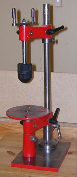 It is completely made from bar stock (a lot of sawing and filing). I found that for the clamping it was necessary to position the screw for the clamping block under the lever so that it just passed the pillar. In my measures the pillar is a 20 mm bar and the clamping blocks 12 mm diameter. that means that I placed the center for the screw for the clamp 13 mm from the center of the pillar bar hole. Then just followed the instructions in the book. The foot is 70 mm diameter turned in very many passes on a Unimat4 clone lathe (which is as big as can be handled I think). For table I found an old face plate from an old B&D electric hand drill. A tad too small in diameter, but works very well for the threading I use the pillar tool for. Hope this gives an idea at least. BR /Peter |
Please login to post a reply.
Magazine Locator
Want the latest issue of Model Engineer or Model Engineers' Workshop? Use our magazine locator links to find your nearest stockist!
Sign up to our Newsletter
Sign up to our newsletter and get a free digital issue.
You can unsubscribe at anytime. View our privacy policy at www.mortons.co.uk/privacy
Latest Forum Posts
- hemingway ball turner
04/07/2025 14:40:26 - *Oct 2023: FORUM MIGRATION TIMELINE*
05/10/2023 07:57:11 - Making ER11 collet chuck
05/10/2023 07:56:24 - What did you do today? 2023
05/10/2023 07:25:01 - Orrery
05/10/2023 06:00:41 - Wera hand-tools
05/10/2023 05:47:07 - New member
05/10/2023 04:40:11 - Problems with external pot on at1 vfd
05/10/2023 00:06:32 - Drain plug
04/10/2023 23:36:17 - digi phase converter for 10 machines.....
04/10/2023 23:13:48 - More Latest Posts...
- View All Topics
Support Our Partners


Shopping Partners
Subscription Offer

Latest "For Sale" Ads
- Reeves** - Rebuilt Royal Scot by Martin Evans
by John Broughton
£300.00 - BRITANNIA 5" GAUGE James Perrier
by Jon Seabright 1
£2,500.00 - Drill Grinder - for restoration
by Nigel Graham 2
£0.00 - WARCO WM18 MILLING MACHINE
by Alex Chudley
£1,200.00 - MYFORD SUPER 7 LATHE
by Alex Chudley
£2,000.00 - More "For Sale" Ads...
Latest "Wanted" Ads
- D1-3 backplate
by Michael Horley
Price Not Specified - fixed steady for a Colchester bantam mark1 800
by George Jervis
Price Not Specified - lbsc pansy
by JACK SIDEBOTHAM
Price Not Specified - Pratt Burnerd multifit chuck key.
by Tim Riome
Price Not Specified - BANDSAW BLADE WELDER
by HUGH
Price Not Specified - More "Wanted" Ads...
Get In Touch!
Do you want to contact the Model Engineer and Model Engineers' Workshop team?
You can contact us by phone, mail or email about the magazines including becoming a contributor, submitting reader's letters or making queries about articles. You can also get in touch about this website, advertising or other general issues.
Click THIS LINK for full contact details.
For subscription issues please see THIS LINK.
Digital Back Issues


Donate

 Register
 Log-in
Model Engineer Magazine
- Percival Marshall
- M.E. History
- LittleLEC
- M.E. Clock

ME Workshop
- An Adcock
- & Shipley
- Horizontal
- Mill

Subscribe Now
- Great savings
- Delivered to your door

Pre-order your copy!
- Delivered to your doorstep!
- Free UK delivery!
All Forum Topics > Workshop Tools and Tooling > Problem making Universal Pillar Tool.