Forum sponsored by:

Meek Type Dog-Clutch for Denford
| Fatgadgi | 26/05/2020 20:57:12 |
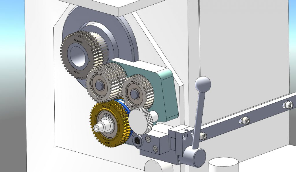
| 188 forum posts 26 photos | Finally, after years of drooling over "Sir" Meek's (and others) dog-clutch threading conversions, I have designed one for my Denford 280 lathe. I've only spent a couple of weeks to get to this stage, so there are still going to be a couple of bugs to iron out, but overall I'm happy. Happy enough to have ordered the materials, in fact, plus a missing 20DP involute gear cutter that I needed, used off flea-bay. The gearing and clutch bits that you see are reasonably well sorted, and I'm OK with the design. The actuation system that is moved by the saddle still needs the detail finalising. And I need one more check to make sure that the gear rotations are in the right direction to match the actuator lever !!!! So, wish me luck ..... if anyone is interested, I will post a few notes on my progress as I start to machine. I promise not to post the rude words when I find the errors Cheers - Will
|
| Graham Meek | 26/05/2020 21:38:31 |
| 714 forum posts 414 photos | Hi Will, I am really glad someone else has picked up the screwcutting clutch gauntlet and is running with it. I am currently starting to put together a version for the Atlas 618 lathe. Thanks to an enquiry from the USA. This has been proving to be one of the hardest to do, due to the peculiarities of how the screwcutting gear train takes its drive, depending on TPI, from one of the two gears on the tumbler shaft. I did think to start with that this would be a reworked version of the ML7 due to the similarities between the two machines, but I was wrong. My Maximat clutch design last year was I thought going to be my last design in this field. I am beginning to know how a type cast actor feels. I wish you well with the design, and if I can be of any help, don't be afraid to ask. Regards Gray, |
| Fatgadgi | 27/05/2020 12:38:26 |
| 188 forum posts 26 photos | Thanks for the reply Gray - and appreciate the offer of advice. So here we go The clutch "dogs" have 1mm per side clearance before engagement, so 2mm in total. Obviously since the threading will hopefully be happening a LOT faster than previously, there is a chance of overrun if there is not enough clearance and the saddle goes too fast, but perhaps at practical speeds the leadscrew stops almost instantly, in which case I need not worry. Do these numbers sound about right to you ?? Good luck with the Atlas - knowing how tricky it was to design around the existing Denford features, I can only imagine how difficult it would be without the lathe in front of you !! Anyway, the first lump of cast iron is due next couple of days for the banjo, so grey dust will be filling the workshop shortly. Bliss. Cheers Will |
| Graham Meek | 27/05/2020 15:31:13 |
| 714 forum posts 414 photos | Hi Will, The travel to trip the clutch at the carriage, on the Myford, and the Hardinge I worked for some time was about 15 to 16 mm, from memory. The travel at the S7 and ML7 clutch units is 2.5 mm, the clearances need be no more than 0.25 mm. The Operating lever stops moving as soon as the Dogs disengage, and the ball bearing detent wants to be close to the neutral position, so that the Operating lever will snap into neutral. Once set the carriage will repeatedly stop in exactly the same position and start in the same position. The only time these settings alter is when you set at a lower speed and then for some reason increase the spindle speed. As you rightly assume it is to do with Moments of Inertia, but once the settings have been reset at the higher speed the carriage will carry on as before. I have always pointed this out when setting up the clutch unit in my articles to make those wary with VFD drives. It was something I found out while using the Hardinge which has variable spindle speeds. Regards Gray,
|
| Fatgadgi | 27/05/2020 19:26:52 |
| 188 forum posts 26 photos | Thanks Gray, I'll reduce the clearance in the clutch. Yes, it's logical that the speed would change the trip position, but that's not a problem once understood. I don't use a VFD, but the lathe has speed control via variable width pulleys, so the same would apply. Cheers Will |
| Fatgadgi | 09/06/2020 19:39:15 |
| 188 forum posts 26 photos | Have not got very far as I type this - I got distracted and made 4 low profile clamps over the weekend to hold the lump of cast iron block for the main body, on the mill. And then work got in the way
I wanted to face both sides of the block as a first operation, which I could have done easily on the lathe. Instead, I finally decided to make some low profile clamps, which I had wanted to make for ages. They follow the principle of some (expensive) proprietry ones I have seen, and they work amazingly well - I was quite surprised actually, not too hard to make and the cam screws worked first time. The Jaws are hardened and tempered tool steel; grooved on one side to bite into rough work, and smooth on the other. Couple more photos in my album - if anyone would like me to add the rough 2D drawings, just ask. So, both sides now faced, and just going back out to the garage now to start machining the detail whilst the boss has gone out to do the food shopping. Cheers - Will
|
| Fatgadgi | 26/06/2020 18:06:57 |
| 188 forum posts 26 photos | I’ve managed to get some evenings in the workshop last couple of weeks, even though the temperature has been a bit on the warm side recently, so I thought an update was in order.
I’ve also managed to machine 3 of the 5 gears, along with a few stub shafts. So good progress.
The Pivot Plate and the gears shown are cast iron, which made a mess of the machines but is easy to machine, but the dog clutch gears will be steel. The picture below shows the original gears, and how they will be replaced with the new one.
I will probably get a start on the clutch parts this weekend, so a bit more gear cutting and rotary table work ..... but now off to fire up the bbq
|
| Graham Meek | 27/06/2020 11:08:22 |
| 714 forum posts 414 photos | Nice work Will, This machine will benefit from the attachment and you will wonder how you ever managed without it before. Regards Gray,
|
| Fatgadgi | 22/07/2020 21:43:23 |
| 188 forum posts 26 photos | Me Again. Time has been disappointingly sparse in the workshop recently due to some domestic diy chores, but I have made some progress. The clutch and clutch gears have been completed along with the associated rotating sleeve components. So the gear assembly is all but finished for this stage - still a couple of holes to machine in situ once I know the position of other parts, and a locking pin to make.
As shown below, I've temporarily tried it in position on the lathe with a change wheel fitted. It fits a treat and the gears all turn as hoped. Result !!!. The gear on the main spindle is still the original one, but because it's a tight fit on the shaft, I will not remove it again until I'm ready to make the change.
Next challenge is to make the clutch actuator arm and the mechanism that moves it. Cheers Will
|
| Fatgadgi | 06/12/2020 21:08:22 |
| 188 forum posts 26 photos | Hi All - It's been a couple of months, so I thought I'd update progress ..... Well, I'm happy with it so far. All the gear and clutch stuff is working well in manual mode, and I've given it some welly without anything dropping off or seizing. Noise is OK, not silent, but no noisier than it was before I attacked it, and it can be disengaged when not needed. The only thing I need to re-do is to swap the detent spring for the lever position - it needs to be stronger to give a more positive location.
I still need to make the auto-release mechanism that connects the clutch mechanism with the saddle position, but the lever arm that it will attach to is in place (under the cover, so not visible).
I have cut the aperture in the gear door, but it needs tidying up. Also the door lock position needs to be moved up, which will need some welding and painting to do it justice. When I'm ready. Even in manual mode, screw cutting metric, which is 99% of the threading I do, has been transformed. No more stopping and reversing the motor between passes !! Cheers Will
|
| Fatgadgi | 14/01/2022 21:40:06 |
| 188 forum posts 26 photos | Hi All Final update …… I retired at Christmas, so my job is now playing in the workshop !! So I’ve blitzed the dog clutch that I started 19 months ago, and finally finished the complete system, with the saddle auto actuation being the last bit. But that’s it, done, and it works a treat !!
The lever system is a bit convoluted, but the saddle feed disengages the threading quite accurately, with a nice satisfying snapping action and a repeatability of few thou at low feed rate, which is great. Worked out a way that didn’t need any welding of the door, just an aperture cut out. Only compromise is that the saddle has lost 50mm of travel at the Chuck end. I can’t say I ever remember needing to move the saddle that close to the headstock, but if required, I’d have to take off the lever. Not the end of the world. So, next project is a CNC’d polarising flash filter holder for my son’s camera. Better finish the drawings - no time to waste 🙂 Cheers Will |


Please login to post a reply.
Magazine Locator
Want the latest issue of Model Engineer or Model Engineers' Workshop? Use our magazine locator links to find your nearest stockist!
Sign up to our Newsletter
Sign up to our newsletter and get a free digital issue.
You can unsubscribe at anytime. View our privacy policy at www.mortons.co.uk/privacy
Latest Forum Posts
- *Oct 2023: FORUM MIGRATION TIMELINE*
05/10/2023 07:57:11 - Making ER11 collet chuck
05/10/2023 07:56:24 - What did you do today? 2023
05/10/2023 07:25:01 - Orrery
05/10/2023 06:00:41 - Wera hand-tools
05/10/2023 05:47:07 - New member
05/10/2023 04:40:11 - Problems with external pot on at1 vfd
05/10/2023 00:06:32 - Drain plug
04/10/2023 23:36:17 - digi phase converter for 10 machines.....
04/10/2023 23:13:48 - Winter Storage Of Locomotives
04/10/2023 21:02:11 - More Latest Posts...
- View All Topics
Support Our Partners


Shopping Partners
Subscription Offer

Latest "For Sale" Ads
- Reeves** - Rebuilt Royal Scot by Martin Evans
by John Broughton
£300.00 - BRITANNIA 5" GAUGE James Perrier
by Jon Seabright 1
£2,500.00 - Drill Grinder - for restoration
by Nigel Graham 2
£0.00 - WARCO WM18 MILLING MACHINE
by Alex Chudley
£1,200.00 - MYFORD SUPER 7 LATHE
by Alex Chudley
£2,000.00 - More "For Sale" Ads...
Latest "Wanted" Ads
- D1-3 backplate
by Michael Horley
Price Not Specified - fixed steady for a Colchester bantam mark1 800
by George Jervis
Price Not Specified - lbsc pansy
by JACK SIDEBOTHAM
Price Not Specified - Pratt Burnerd multifit chuck key.
by Tim Riome
Price Not Specified - BANDSAW BLADE WELDER
by HUGH
Price Not Specified - More "Wanted" Ads...
Get In Touch!
Do you want to contact the Model Engineer and Model Engineers' Workshop team?
You can contact us by phone, mail or email about the magazines including becoming a contributor, submitting reader's letters or making queries about articles. You can also get in touch about this website, advertising or other general issues.
Click THIS LINK for full contact details.
For subscription issues please see THIS LINK.
Digital Back Issues


Donate

 Register
 Log-in
Model Engineer Magazine
- Percival Marshall
- M.E. History
- LittleLEC
- M.E. Clock

ME Workshop
- An Adcock
- & Shipley
- Horizontal
- Mill

Subscribe Now
- Great savings
- Delivered to your door

Pre-order your copy!
- Delivered to your doorstep!
- Free UK delivery!
All Forum Topics > Manual machine tools > Meek Type Dog-Clutch for Denford