Forum sponsored by:

Hobbymat /Prazi D-bed 'watchmakers' lathe - adjustment?
| Barry Johnson 2 | 05/06/2017 14:09:15 |
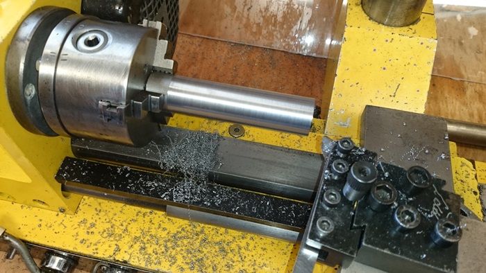
| 5 forum posts | Hi all I have a Hobbymat MD65 lathe (AKA Prazimat SD300), which has a 'D'-shaped bed. A year or so ago I found that it is turning a taper: 0.16mm difference in diameter over an 80mm length (tapered towards the tailstock end). Before I take drastic action and undo the pinch bolts that clamp the bed into the head and start attempting to re-align the bed, I'm looking for some advice - preferably from someone who has done this before... Note that the bed is not directly attaced to the lathe base, so the usual method of twisting the base will not work (I think). This error makes the lathe useless for turning long thin things - fortunately most of what I do is short and fat. I have replaced the spindle bearings, adjusted the carriage gibs and various other attempts - none of them had any effect. The "good" news is that the 0.16mm difference in diameter remained constant throughout - meaning I have now eliminated several other potential sources of the error (and also not made things any worse!). There is more info below, but the above is really the crux of my question. Any help gratefully recieved! Here's a pic showing the test bar, d-bed, head and spindle. The d-bed is held in the head with two pinch bolts - you can just see one in the lower left corner.
To take my measurements I turn up a test bar held only in the chuck, and them measure the diamter at the chuck end, and again at the free end. The difference in diameter is rock steady at 0.16mm. I attached a clock to the carriage and ran it up and down the length, my findings were curious (to me anyway):
More measuring and I found that the tool height changes along the length of the test piece (confirming the dial gauge readings above). I find it curious that all of the error is on the bottom and far side - this suggests that the bed is exaclt equally out of alignment in the vertical and horizontal planes. Thanks B |
| John Haine | 05/06/2017 15:02:01 |
| 5563 forum posts 322 photos | If you can borrow or buy an MT2 test bar which is turned and ground parallel over its length concentric with the MT2 taper, you can get a better idea of alignment without potentially getting confused with how the lathe turns. Having said that you are seeing an effective misalignment of 80 microns in 80 mm which doesn't strike me as being bad for what is basically a low cost lathe. |
| Barry Johnson 2 | 05/06/2017 15:44:57 |
| 5 forum posts | Hi John - the MT2 test bar is a good idea if I do bite the bullet and attempt a re-alignment. Still got to figure out how I might go about this though... any ideas gratefully recieved! A "low cost lathe" - the cheek! OK so it may be only a little lathe but I used to see 0.033mm difference in diameter over 80mm (so 16 microns). At one point I had the milling head attached and attempted milling on the lathe - this lathe is not very rigid and I gave up after lots of chatter. I suspect that this exercise has made a bad situation (0.033mm) even worse (0.16mm). B |
| Bazyle | 05/06/2017 20:59:49 |
 6956 forum posts 229 photos | You are doing this with the saddle and not the topslide? |
| Barry Johnson 2 | 06/06/2017 11:19:51 |
| 5 forum posts | Hi Bazyle - yes I am taking the cut with the topside locked, and always in towards the chuck. Have done same with collet holder inserted into the MT2 spindle bore, with same measured error. All evidence points to bed misalignment. What I'm really looking for is any advice/tips/suggestions on how I might physically re-align the bed. I was thinking of using a test bar in the spindle as a reference, and then simply loosen the pinch bolts and attempt to gently tap the bed into alignment, using something soft-faced. The way appears to be straight as best I can measure, I.e. not bent. Also the taper is consistent over the 80mm, as I have taken measurements at 10mm intervals and checked them against expected diameter. Cheers B |
| Bazyle | 06/06/2017 13:04:50 |
6956 forum posts 229 photos | Perhaps just loosening the tail end support bolts and tapping that would work. Although it implies bending the main bed bar that is the equivalent of twisting the bed of a conventional lathe. In reality the bed bar is more of a guide and the square base is the bed. |
| Lambton | 06/06/2017 16:09:50 |
 694 forum posts 2 photos | Barry, May I suggest that you try using a smaller diameter piece of stock for taking your test cuts. I say this because it looks, from your photo, that the test piece is only being held by the outside half of the chuck jaws. It would be much better to have a bar the just passes right into the chuck and so would be gripped by the whole length of the jaws. I my experience it is best to have the most rigid set-up possible if the highest possible precision is needed. It might be worth putting your DTI at the outer top end of your existing test bar and just pushing the bar upwards gently with one finger simulating what happens when taking a light cut.. I think you will be very surprised how much the bar moves. Eric
|
| Barry Johnson 2 | 06/06/2017 19:29:56 |
| 5 forum posts | Hi again Bazyle - yes that sounds like an idea, although the deflection required at the far end to correct the error is in the region of 1mm, which is a lot for a 40mm bar... Because I know that the error has worsened (from 0.033), and that the bed is straight, I believe that the bed has become cocked in its bore. I am happy to be told otherwise! However all my many measurements and tests to date have all shown a 0.16mm error, even after replacing the spindle bearings. Hi Eric - thanks for the advice, I will do as you suggest when I get home. I have read that the largest possible diameter is best for a test bar, and have followed Harold Hall's advice on the 25mm size of mine. The lathe is very small, the bore through the chuck is about 16mm... Provided I don't damage the bed itself, I don't think I have much to lose by giving it a go releasing the pinch bolts and tapping it into place - maybe famous last words but I don't think I'm going to make things worse. I have ordered an MT2 test bar - if measurements off the test bar confirm the 0.16mm error then I will go ahead with this (possibly ill-advised) plan... |
| Nicholas Farr | 06/06/2017 22:14:57 |
 3988 forum posts 1799 photos | Hi Barry, I can't see what you would achieve by loosening the D bed, as this is just clamped into a machined hole through the headstock. You have three bolts in the headstock below the D bed, the two outside ones just nip the bed by closing the hole through the headstock onto the D bed, as this hole has a cut along it's length at the bottom. The middle bolt of the three will just ease the hole open enough to be able to remove or rotate the D bed. The only adjustment you will get is rotating the D bed, but of course, this will then throw your saddle and also your tailstock out of alignment. If you throw the saddle out of alignment, this will then bind on the lead-screw. It may pay to make sure that the bolts holding the headstock to the baseplate have not loosened and allowed the headstock to twist out of line with the tail end of the baseplate, which will have the same affect as trying to push the tail end of the D bed on it's support plate. You will have to turn the lathe onto the back side and remove the electric board, which is held on by five screws, to get to the headstock bolts. Regards Nick. |
| Barry Johnson 2 | 07/06/2017 12:03:41 |
| 5 forum posts | Hi Nick - I can't disagree with you, I think it unlikely that the bed will move in its bore. However, something has changed to increase the error. Thanks for the suggestion about the head bolts, however I have checked that the end of the way is not being pulled out of line by the plastic support plate. |
Please login to post a reply.
Magazine Locator
Want the latest issue of Model Engineer or Model Engineers' Workshop? Use our magazine locator links to find your nearest stockist!
Sign up to our Newsletter
Sign up to our newsletter and get a free digital issue.
You can unsubscribe at anytime. View our privacy policy at www.mortons.co.uk/privacy
Latest Forum Posts
- *Oct 2023: FORUM MIGRATION TIMELINE*
05/10/2023 07:57:11 - Making ER11 collet chuck
05/10/2023 07:56:24 - What did you do today? 2023
05/10/2023 07:25:01 - Orrery
05/10/2023 06:00:41 - Wera hand-tools
05/10/2023 05:47:07 - New member
05/10/2023 04:40:11 - Problems with external pot on at1 vfd
05/10/2023 00:06:32 - Drain plug
04/10/2023 23:36:17 - digi phase converter for 10 machines.....
04/10/2023 23:13:48 - Winter Storage Of Locomotives
04/10/2023 21:02:11 - More Latest Posts...
- View All Topics
Support Our Partners


Shopping Partners
Subscription Offer

Latest "For Sale" Ads
- Reeves** - Rebuilt Royal Scot by Martin Evans
by John Broughton
£300.00 - BRITANNIA 5" GAUGE James Perrier
by Jon Seabright 1
£2,500.00 - Drill Grinder - for restoration
by Nigel Graham 2
£0.00 - WARCO WM18 MILLING MACHINE
by Alex Chudley
£1,200.00 - MYFORD SUPER 7 LATHE
by Alex Chudley
£2,000.00 - More "For Sale" Ads...
Latest "Wanted" Ads
- D1-3 backplate
by Michael Horley
Price Not Specified - fixed steady for a Colchester bantam mark1 800
by George Jervis
Price Not Specified - lbsc pansy
by JACK SIDEBOTHAM
Price Not Specified - Pratt Burnerd multifit chuck key.
by Tim Riome
Price Not Specified - BANDSAW BLADE WELDER
by HUGH
Price Not Specified - More "Wanted" Ads...
Get In Touch!
Do you want to contact the Model Engineer and Model Engineers' Workshop team?
You can contact us by phone, mail or email about the magazines including becoming a contributor, submitting reader's letters or making queries about articles. You can also get in touch about this website, advertising or other general issues.
Click THIS LINK for full contact details.
For subscription issues please see THIS LINK.
Digital Back Issues


Donate

 Register
 Log-in
Model Engineer Magazine
- Percival Marshall
- M.E. History
- LittleLEC
- M.E. Clock

ME Workshop
- An Adcock
- & Shipley
- Horizontal
- Mill

Subscribe Now
- Great savings
- Delivered to your door

Pre-order your copy!
- Delivered to your doorstep!
- Free UK delivery!
All Forum Topics > Workshop Tools and Tooling > Hobbymat /Prazi D-bed 'watchmakers' lathe - adjustment?