Forum sponsored by:

Boxford STS Screwcutting Clutch
| Tony Ray | 05/03/2021 07:24:49 |
| 238 forum posts 47 photos | I can’t immediately see how the Boxford solution is going to be work with the banjo in its current location.
|
| Graham Meek | 05/03/2021 11:35:41 |
| 714 forum posts 414 photos | Hi Tony, Harrison have surely made this one difficult with the banjo pivoting about the output gear. Relocating the banjo to the more conventional position about the input to the screwcutting box might need a whole new banjo design. My inclination suggests taking the drive from the output shaft, 1:1, to a gearbox containing the clutch directly above the output shaft, there is plenty of room here, but part of this space will be taken up by the banjo movement. The drive is then brought back to this output shaft either by gearing or by a timing belt, 1:1. Failing that the obvious place to fit the clutch is inside the headstock, but that will be major work and not for the faint hearted. Regards Gray, |
| Clive Foster | 05/03/2021 14:34:01 |
| 3630 forum posts 128 photos | Tony If the banjo is re-made to swing off the gearbox in the conventional manner there seems to seem to be about 30 mm behind the current drive gear position. Maybe a bit more if the actual gearbox input gear can move outwards a little. Probably be enough room for a concentric arrangement, as used by P&W, with the single tooth clutch unit keyed to the shaft behind a free running drive gear. Basic idea would be to fit a hollow shaft over the existing drive shaft engaging in the existing key. The drive gear runs free on this hollow shaft. The clutch device is keyed or splined to the hollow shaft and pushed in or out of engagement with the dog on the gear by the actuator forks. It would be best if the engagement operation were done via a proper thrust bearing so the forks and carrier don't rotate. With a thrust bearing a simple Y fork, pin and ring actuator would suffice. The hollow shaft needs to be very firmly fixed to the drive shaft lest engagement forces wallow out the existing key. When trying to scheme out something for my 1024, before Graham showed us all how to do it, I sketched a concentric system using a rotating "balls on ramps" thrust actuator rather like that used for clutch operation on some British motorcycles. Probably not enough room for that sort of system here. Big attraction is that positive in or out hold can be done with a simple tension spring direct on the operating arm arranged to move in a over centre arc. The 1024 was always going to have electrical knock off as there is no way through for mechanical levers. Have a husky solenoid unit out of a pre-engaged car engine starter tucked away in the useful box for that job. Clive |
| Tony Ray | 05/03/2021 18:20:38 |
| 238 forum posts 47 photos | Its going to take me a while to process all of that useful info, I spent a bit of time this afternoon looking at the possibilities. This is the banjo in its upper most position, this reduces the space envelope to approx 40 x 90mm. I think I will need a more detailed explanation a new a sketch to understand Gray’s suggestion.
|
| Tony Ray | 05/03/2021 18:46:30 |
| 238 forum posts 47 photos | I don’t think I would want to attempt an internal mod without a spare box to work on so here is a preliminary look at moving the banjo. The boss supporting the input shaft to the gearbox is cylindrical but smaller in dia that the current banjo and has protruding cap heads but they can be changed. A sleeve could be made to make up the difference. I hung the banjo on the boss with the two sets used to cut metric pitches. 22T on the output
so my initial conclusion is that this could work , the banjo is not a complicated part to make and I can 3 d print mock-ups. I think I need to make an accurate model in Fusion360 then model the various gear trains needed to cut imperial, module and DP. I am fortunate to all have a full set of change wheels to do Imperial threads although recent experiments have yielded useable 3D printed items. Moving the banjo then gives a large space in which to implement the dog clutch. That will of course need to be figured out but it should be possible to use Trevors excellent solution as a starting point. |
| Tony Ray | 05/03/2021 18:48:29 |
| 238 forum posts 47 photos | Just noticed that I failed to swap the compound gears for the 44T set up. |
| Clive Foster | 05/03/2021 19:33:47 |
| 3630 forum posts 128 photos | Tony This is how P&W do it but they slide the gear. I see no reason why the clutch unit rather than the gear couldn't do the sliding. With a decent helping of low cunning I think it might well be possible to squeeze something similar onto the existing drive output shaft.
Dog is a pin (J -723-C) pushed into the gear (G 10-42-'37) clutch is on the right (J -742 B). Clutch is made as part of a sleeve sliding on and keted to the drive shaft. Gear and actuator slide on the outside. Sorry for the poor quality but the scan I have is what it is. Clive Edited By Clive Foster on 05/03/2021 19:37:32 |
| Graham Meek | 06/03/2021 11:55:16 |
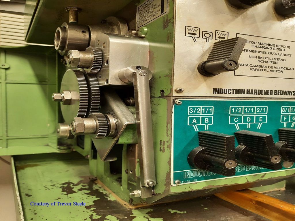
| 714 forum posts 414 photos | Hi Clive, I am not familiar with this lathe, but from what I can make out from the scan. The P&W clutch drives in one direction only. If this is correct then the leadscrew clasp nuts need to be disengaged to return the carriage to the start position. The Hardinge HLV clutch, which the original Myford, and all my subsequent designs are based on, drive in both directions. There is no need with these designs to disengage the leadscrew clasp nuts. This makes cutting any Thread, DP or Module dead simple. With no reversal of the motor needed either. Regards Gray, Hi Tony, As I said earlier, this is not going to be easy, and somewhere compromises have to be made. If you look back up this post to the clutch fitted to my Maximat. You will see the clutch proper is in front of the original output shaft from the headstock and below it. The final output from this clutch goes via 3 gears to the output shaft. which is on the same radius from the screwcutting box as the original output shaft was. Turn this type of assembly through 90 degrees CW and you will have a similar unit to fit your lathe. More detailed shots of the Maximat unit can be found in My Album. Regards Gray,
Edited By Graham Meek on 06/03/2021 11:56:04 |
| Tony Ray | 06/03/2021 11:59:09 |
| 238 forum posts 47 photos | Some great ideas here, not being blessed with a mechanically minded brain I have a question about the P&W clutch Clive: Am I correct in thinking that the output shaft direction of rotation is handled by another means not shown in the diagram? I like the idea of electromechanical actuation, that could solve the issues around sensitivity that Trevor is working on, I would think that suitable micro switches on a stop bar with an E stop as a fail safe would work. Your idea Clive of a DRO output stop signal is a good one and would not I think be difficult for someone with the right skill set but perhaps a full implementation of Clough42’s electronic leadscrew would be another solution. Trevor has kindly sent me the cad files and introduced me to Nanocad so I can view them - many thanks Trevor. Anyway off to the Workshop to get a better idea of what I have to work with. |
| Clive Foster | 06/03/2021 13:59:39 |
| 3630 forum posts 128 photos | Graham, Tony The P&W has two single tooth clutches, one for forward feed / screwcutting and one for reverse. There is no provision for reversing spindle rotation. Found another picture and clipped the relevant parts showing both clutches. The actual gear train drive path for forward & reverse is "complicated".
Its arguable that P&W designed the whole machine around exploiting the single tooth feed clutches. The main drive clutch lives in an oil tight box on the back of the machine with matching holes in headstock and box so the drive gear on the output side of the clutch can poke through to meet the input gear on the main speed selection box. Control via a lever on the saddle which rotates the stop rod. Push down for forward, pull up for reverse. Stop rod is 7/8" diameter with appropriately massive clamps.
Fine adjustment thimble on the left side of the saddle too. Its very convenient. Have to remember to stop the spindle with the main clutch above 300 rpm before using the single tooth clutches. Clive Edited By Clive Foster on 06/03/2021 14:04:21 |
| Tony Ray | 08/03/2021 07:18:17 |
| 238 forum posts 47 photos | Thanks for the detailed explanation of the P&W which I don’t fully understand but I ‘m sure will prove useful to others and maybe myself in developing an M250 solution. |
| Tony Ray | 08/03/2021 07:49:48 |
| 238 forum posts 47 photos | Ok I think I have the STS solution figured out, I had a light bulb moment last night so here goes: A 30T gear fitted with a drive dog is fixed to the output shaft from the lathe . Engaged with this gear is a 15T idler that is wider so that it engages with a second 15T idler which then drives a second 30T gear also fitted with a drive dog that is free to rotate on the final output shaft. The two dog gears face each other and interposed is a clutch plate that is slid either to the left or to the right to engage with either drive dog. The clutch plate is keyed to the final output shaft. When slid to the right the clutch plate and therefore the final output shaft is driven in the same direction of rotation as the lathe output shaft. When slid to the left it rotates in the opposite direction because the second dog gear is driven off the first dog gear via two idlers which reverse the rotation. Because the idlers have the same 15T tooth count and both dog gears 30T the final output shaf rotates athletic same speed as the lathe output shaft no matter which way the clutch is driven. Finally for the sak of completeness the clutch is actuated with manual via the knobbed lever that project towards the from of the lathe or by the trip mechanism which runs down to the trip bar. I think that it, this will help me figure out what my solution.
|
| Clive Foster | 08/03/2021 10:00:31 |
| 3630 forum posts 128 photos | Tony Sounds like that will work just fine. But the M250 has a feed reverse already so one bi-directional clutch will do the deed. The drive pin doesn't care which side of the dog it engages with. So it all becomes much simpler as only two gears are needed and everything can be concentric. Need to change the label on the headstock forward / reverse feed selector knob tho' as the output drive gear will now be running backwards. Anyway thanks to this discussion I've had my own light bulb moment as to how to do the job on my 1024. Also concentric and geared down with bi directional clutch but inside out and back to front with the input gear free running. Clive Edited By Clive Foster on 08/03/2021 10:25:13 |
| Graham Meek | 08/03/2021 11:25:31 |
| 714 forum posts 414 photos | Hi Tony, Your solution will work fine and is exactly how Trevor and I worked out the STS set-up. The automatic trip mechanism for the stops can be a bit more tricky to fit, but the permutations here are endless. While the trips to the rear of the bedway are usually more compact as regards any lever lengths. Having them at the front abutting the apron will make it more convenient. Having the internal feed direction change within the headstock is fine for doing left hand threads, or when the banjo set-up has an additional stud in the train from what it normally does. Once set, this internal gearing cannot be altered, as this will up-set your synchronisation point in the dog-clutch, by a factor of how many teeth are involved in the internal reversing gear. Regards Gray,
|
| Tony Ray | 08/03/2021 23:51:03 |
| 238 forum posts 47 photos | Clive: I’m glad I was of help in a “But I didn’t do anything” kind of way. Thanks Gray & Clive for confirming my understanding of the STS solution, it is not yet my solution for the Harrison, and finally thanks also Gray for ansewingbwhat was going to be my next question regarding the use of the lathes existing fwd / rev knob. |
| Graham Meek | 09/03/2021 10:24:13 |
| 714 forum posts 414 photos | Hi Tony, This may, or may not be possible, but the idea has just come to me. As regards the Banjo, provided there is sufficient depth within the cover, the Banjo could remain at its current position, but be outboard of the screwcutting clutch. The gear clusters on the Banjo being mounted on the inside of the Banjo rather than the outside as they currently are. A Steel plate Banjo would not need to be as thick as a Cast Iron one. I know this might be a bit fiddly when setting up a gear train, but the need to change the set-up is fairly infrequent in my experience. Regards Gray, |
| Clive Foster | 09/03/2021 14:47:25 |
| 3630 forum posts 128 photos | Tony, Graham I'm struggling with similar space and output gear drive boss issues on the 1024. I have about 1" space behind the plane of the output gear and 1 1/2" in front of the plane of the banjo gear to play with. There is some upwards space above under a cover.
I have the 127 - 120 metric to imperial conversion gear pair permanently mounted so I only need to swop the spacer and gear order at the gearbox input to change. Headstock feed drive gear normally meshes with the 120 tooth transfer gear hiding behind the 127 gear in the picture. I propose to use a concentric system with bi-directional clutch tucked over to the left of the picture. Something like this :-
Input gear and clutch body share a common splined or keyed shaft. Gear fixed, clutch sliding. The output gear is free running. The 127 and 120 tooth conversion gear pair will be reversed putting the 120 tooth gear on the outside to mesh with the clutch system output gear. An intermediate gear, not shown, will be needed to transfer drive from output gear to banjo gearing to avoid clashing with the 127 tooth gear which now lies on the same plane as the headstock feed drive gear. Hopefully it will all sqeeze in. Clive
|
| Graham Meek | 09/03/2021 17:41:49 |
| 714 forum posts 414 photos |
This is the cross section through the Maximat Clutch, note the one Dog gear takes its drive directly from the wider output gear from the headstock' This gear also meshes with the idler gear shown below to reverse the direction to the other Dog gear. (Shown in mesh).
The above are the elements necessary to make the dog clutch work on the Maximat.
Above are the two Dog gears, the Double sided Dog clutch and the output gear on the Clutch shaft. Only the Dog clutch is keyed to the Clutch shaft. Drive to the output gear is only achieved by selecting a direction with the control lever.
This connects to the stop rod which carries the stops.
These then are the elements required for a successful clutch. Regards Gray, |
| Tony Ray | 09/03/2021 18:32:04 |
| 238 forum posts 47 photos | Hi Clive, as you say you don’t have a lot of room to work with. The operation of you coaxial clutch is straightforward and I’m assuming that that’s a schematic as there looks like a lot of opportunities to make it more compact. Unlike you I need to change form metric to imperial quite regularly as I only have one machine. I would imagine you have the P&W for imperial and the S&B for metric? |
| Tony Ray | 09/03/2021 18:44:53 |
| 238 forum posts 47 photos | Hi Gray, I will keep the alternative banjo idea in mind but I’m going to try to develop the second shaft arrangement. Your comment re keeping the new output shaft on the same circle in relation to the input shaft he to screw cutting box was very helpful. I lie the idea of using an HTD belt to transfer motion to the new shaft but the shortest length seems to be 300mm so it might need a jockey wheel to fold it into the space required. I think relocating the banjo is not going to be an issue and one I can manage. Thanks for future explaining the your Emco version, what is the piurpose of the other gears that are in it ? Regards Tony |


Please login to post a reply.
Magazine Locator
Want the latest issue of Model Engineer or Model Engineers' Workshop? Use our magazine locator links to find your nearest stockist!
Sign up to our Newsletter
Sign up to our newsletter and get a free digital issue.
You can unsubscribe at anytime. View our privacy policy at www.mortons.co.uk/privacy
Latest Forum Posts
- hemingway ball turner
04/07/2025 14:40:26 - *Oct 2023: FORUM MIGRATION TIMELINE*
05/10/2023 07:57:11 - Making ER11 collet chuck
05/10/2023 07:56:24 - What did you do today? 2023
05/10/2023 07:25:01 - Orrery
05/10/2023 06:00:41 - Wera hand-tools
05/10/2023 05:47:07 - New member
05/10/2023 04:40:11 - Problems with external pot on at1 vfd
05/10/2023 00:06:32 - Drain plug
04/10/2023 23:36:17 - digi phase converter for 10 machines.....
04/10/2023 23:13:48 - More Latest Posts...
- View All Topics
Support Our Partners


Shopping Partners
Subscription Offer

Latest "For Sale" Ads
- Reeves** - Rebuilt Royal Scot by Martin Evans
by John Broughton
£300.00 - BRITANNIA 5" GAUGE James Perrier
by Jon Seabright 1
£2,500.00 - Drill Grinder - for restoration
by Nigel Graham 2
£0.00 - WARCO WM18 MILLING MACHINE
by Alex Chudley
£1,200.00 - MYFORD SUPER 7 LATHE
by Alex Chudley
£2,000.00 - More "For Sale" Ads...
Latest "Wanted" Ads
- D1-3 backplate
by Michael Horley
Price Not Specified - fixed steady for a Colchester bantam mark1 800
by George Jervis
Price Not Specified - lbsc pansy
by JACK SIDEBOTHAM
Price Not Specified - Pratt Burnerd multifit chuck key.
by Tim Riome
Price Not Specified - BANDSAW BLADE WELDER
by HUGH
Price Not Specified - More "Wanted" Ads...
Get In Touch!
Do you want to contact the Model Engineer and Model Engineers' Workshop team?
You can contact us by phone, mail or email about the magazines including becoming a contributor, submitting reader's letters or making queries about articles. You can also get in touch about this website, advertising or other general issues.
Click THIS LINK for full contact details.
For subscription issues please see THIS LINK.
Digital Back Issues


Donate

 Register
 Log-in
Model Engineer Magazine
- Percival Marshall
- M.E. History
- LittleLEC
- M.E. Clock

ME Workshop
- An Adcock
- & Shipley
- Horizontal
- Mill

Subscribe Now
- Great savings
- Delivered to your door

Pre-order your copy!
- Delivered to your doorstep!
- Free UK delivery!
All Forum Topics > Manual machine tools > Boxford STS Screwcutting Clutch