Forum sponsored by:

Emco Compact 5 Modifications
| Jouke van der Veen | 28/07/2022 08:53:36 |
| 203 forum posts 19 photos | Good morning Gray, Just another question. What did you do with the base of the tail stock. Did you make it adjustable or is it a fixed correction of alignment with the head spindle? Regards |
| Graham Meek | 28/07/2022 11:46:59 |
| 714 forum posts 414 photos | Good morning Jouke, No problem with questions, it is how we learn things. The Lathe was an Old Stock item which had been sitting in a shop for years still boxed. One would have thought it would be in tip-top condition. However the Tailstock alignment was off by quite a bit. I did take the headstock off to see if this had been disturbed in transit but no such luck. Correcting the original machined set up was always going to be a problem. If the flat at the rear of the bed is just 0.03 higher than it should be. Then this will throw the tailstock out of alignment both vertically and horizontally, towards the operator. The body pivoting about the front vee way, and of course visa versa. Thus in order to get the machine up and running, many years back, I bought a second hand Tailstock. I knew this was never going to be right for the lathe, which it was not, so I went about making a new base and modifying this new Tailstock body. The separate base follows any standard Tailstock design with a transverse location tongue to keep things aligned and some form of adjustment to bring the whole on centre line. There is a convenient hole in the rear of the body as standard and through this hole I can access two Allen grubscrews. The larger M6 grubscrew is drilled through to allow the Allen key to reach the smaller M5 grubscrew which is in front. Both screws are in a large headed pin which is pressed into the new base and sits in a convenient cavity. This Pin protrudes down far enough to engage with a hole in the clamping plate which stops this rotating during movement up the bedway, or during tightening and loosening. The M5 impinges on the internal face of the body and moves the whole body towards the Operator. The M6 works on the rear wall of the Tailstock body and takes it in the other direction. This screw is off course turned anti-clockwise to achieve this. Once the machine is turning parallel between centres the two screws are locked by opposing forces. One of my next jobs is to rectify the old Tailstock body. Perhaps I will show later on how I go about doing this. Hope this helps, Regards Gray,
|
| Kiwi Bloke | 28/07/2022 11:52:33 |
| 912 forum posts 3 photos | Gray, fascinating as ever. Some time ago, I asked whether the Compact 5 should be taken seriously. Clearly, it can be - eventually. Emco Holz un Hobby's new saddle looks interesting. Am I right in thinking that it has been threaded as the feedscrew's main 'nut', but also has an adjustable, anti-backlash nut deeper down the feedscrew's bore? It would be nice to have all the female threads easily replaceable. [edit - our posts 'crossed'] Now I'm also waiting eagerly for tailstock mod details. Now you have a vertical unit for your Unimat, I'm waiting eagerly for your upgrade of the spindle bearings... We ask a lot of you, don't we?. Edited By Kiwi Bloke on 28/07/2022 11:56:10 Edited By Kiwi Bloke on 28/07/2022 11:56:32 Edited By Kiwi Bloke on 28/07/2022 11:57:01 |
| Jouke van der Veen | 28/07/2022 12:59:03 |
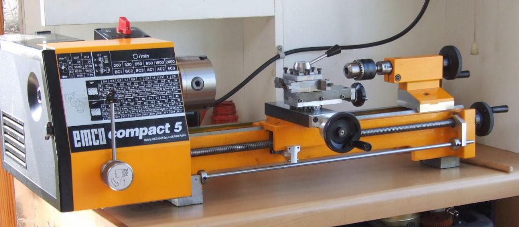
| 203 forum posts 19 photos | Hello Gray, Thank you for your complete explication of the tailstock modification. It looks so simple on the picture on top of this topic but it is not! When you rectify the old tailstock body it would be nice, as Kiwi said, to follow all your progress, at least in this topic. Kiwi, the thread you see in the carriage is for the hollow “top nut” to compress the adjustable anti-backlash nut behind it. The anti-backlash nut is locked against rotation by an “excentric” hollow pin in the small hole through the carriage. I think you can find this in the Emco C5 manual. Regards, Jouke Edited By Jouke van der Veen on 28/07/2022 13:01:54 |
| Kiwi Bloke | 28/07/2022 22:46:38 |
| 912 forum posts 3 photos | Jouke - thanks, understood. So it looks like the new saddle is strictly a replacement for the later model saddle, as you mentioned in your earlier post. If it's used with the earlier cross-slide and feedscrew, about 1cm 'inwards' travel will be lost, perhaps? Graham Meek will doubtless address this by a modified cross-slide feedscrew bracket. |
| Graham Meek | 29/07/2022 10:16:34 |
| 714 forum posts 414 photos | Posted by Kiwi Bloke on 28/07/2022 22:46:38:
Jouke - thanks, understood. So it looks like the new saddle is strictly a replacement for the later model saddle, as you mentioned in your earlier post. If it's used with the earlier cross-slide and feedscrew, about 1cm 'inwards' travel will be lost, perhaps? Graham Meek will doubtless address this by a modified cross-slide feedscrew bracket. My lathe was one of the last of the Yellow models with the latest cross-slide fitting, according to the serial number. As an upgrade I fitted the ball bearing feedscrew bracket. This also removed the need to keep moving the topslide from one location to the other as it allows the cross-slide to go a further 15 mm inwards. The downside of this is the feedscrew is now not long enough as regards the outward movement. This is not a problem as a new longer feedscrew will put things right, but, it may mean drilling the feedscrew clearance hole on through the carriage. As yet I have not checked or made the new feedscrew, it is on the "to do" list. Thus fitting the ball bearing bracket to an older lathe should give an additional 5 mm of inwards travel when combined with fitting the new carriage. Regards Gray, |
| Jouke van der Veen | 29/07/2022 11:12:41 |
| 203 forum posts 19 photos | Gray, Do you need additional gib screws for the longer cross-slide travel? It could be that you do not need to driill the feedscrew hole completely through but only deeper (the original casted carriage has an extra “dead” space between feedscrew hole/space and backwall). Jouke
|
| Graham Meek | 29/07/2022 17:47:54 |
| 714 forum posts 414 photos | Jouke, I have not altered the standard Emco cross-slide in any way. Thanks for the info on the depth of the hole in the cross-slide. this will make fitting the replacement feedscrew easier if what you say is the case. Regards Gray,
Some while back after completing the Retracting Topslide I promised those following this post some photographs on cutting the 10 TPI Worm for my 40:1 Dividing attachment.
I must admit I would not want to cut such a coarse thread on the Compact 5 without the screwcutting clutch. My nerves nor reactions could stand it.
Here is a closer view of the work in progress. I was just about to check the size using the wires in the foreground. At this point there is a further 0.2 mm to be removed.
While I had laid out all the Metric gear trains in the design stage of the screwcutting clutch, there is always one that will bite back. On all the other gear trains the 72T gear is mating with the 20T output gear on the Clutch. However with 10 TPI the 72T gear is lower down in the train and as such it would, if mounted on the standard quadrant mesh with the smaller Tufnol Idler gear in the output train from the Clutch. To get by I have made an off-set mounting block this drops down the 72T gear 16mm below the normal centreline of the quadrant. Thus another "Round to it" for the "To Do" list, is to make a new quadrant with a double row of slots to take the offending gear. This is not such a bad thing as the standard quadrant is now too long and I do consider it to be on the flimsy side. Regards Gray, |
| Graham Meek | 19/08/2022 17:08:24 |
| 714 forum posts 414 photos | Just before the last heat wave I made a start on something I have been meaning to do for a good many years on the Compact 5. I have felt for a long time the tailstock should have an adjustable dial. Graduations are provided on the C5's little brother the Unimat and to be honest it is something I miss.
While adding the dial advantage was taken to incorporate two Radial Ball races. This mod alone is well worth the extra work. Drilling is now a doddle compared to how it was previously.
In order to accommodate the bearings a longer feedscrew was required. This also allowed the bearing housing to be made longer to take the Dial backing ring which carries the Zero line. This is adjustable to suit the operators preference. Rather than have the dial rotating on the plastic of the handwheel and all the stick-tion problems that brings. I have made a separate steel sleeve which uses my trusty friction spring from the Myford Super 7 Handwheel dial. A peg at the back of the sleeve stops this rotating. The dial I have made from aluminium and while I was at it I have made two more to replace the leadscrew and cross-slide plastic dials. I cannot show the finished unit as I need to finish the 40:1 Dividing attachment to allow me to do the graduations on the dials. More details soon. Regards Gray, |
| Graham Meek | 16/09/2022 17:07:13 |
| 714 forum posts 414 photos |
Following on from John's 3D image here is the Embryo Dial in-situ on the lathe. Work can now start on engraving the dial as the Dividing attachment is now finished
This first photograph shows the stand alone unit and how it drives the original C5 Dividing attachment. The worm gear is shown being screwcut earlier.
This is the unit bolted in position. The next view shows the additional dividing plates and a spare wormwheel, along with the homemade single point cutter. The detent has a hold out facility like most larger dividing heads, which avoids the detent being held out of engagement when doing multiple turns of the worm.
This last photograph shows work is about to start on the engraving of the Tailstock dial. Which hopefully will be followed by new dials for the cross-slide and leadscrew.
This is where the C5 and Proxxon merge, note the adaptor plate beneath the Dividing attachment. The complete attachment is on dowels to locate off the central Tee Slot. Thus it can be removed and re-fitted at will. A single dowel that the Dividing attachment abuts in the adaptor plate. Along with the step in the adaptor plate means the Dividing attachment can be removed and returned to the adaptor plate with out the need for clocking. Regards Gray,
Edited By Graham Meek on 16/09/2022 17:11:36 |
| Graham Meek | 23/09/2022 15:32:50 |
| 714 forum posts 414 photos |
This view shows I have now completed all the new and replacement Dials for the Compact 5.
Here is the Tailstock dial which started the ball rolling in the first place.
This is my take on the Leadscrew Dial. I decided to stamp the numbers as per normal practice. Unlike the original dial which has the numbers parallel to the leadscrew axis. I had made provision for stamping the dials to comply with the original, but it involved a lot of extra work. If I cannot get on with this new set-up then I can always bite the bullet and make a new dial.
The cross slide dial is a much better fit as regards the gap between the dial and the endplate when compared to the standard dial. All dials are much smoother in use with none of the sticking that was present with plastic on plastic.
When I fitted the Retracting Topslide attachment I thought my original adjustable dial that I had made for the Unimat 3 Restoration looked a little on the small side. I therefore decided to make a new larger version which follows the rest of the machine. The new dial does allow the numbers to ascend in 0.2 of a millimetre. This could not be done on the original Unimat dial as the numbers all ran into one another. I hope to post the restoration of the ailing C5 Tailstock soon. Regards Gray, |
| Jouke van der Veen | 24/09/2022 14:48:41 |
| 203 forum posts 19 photos | Hello Gray, When I see all your improvements coming along for the Emco C5 I am often wondering about which machines you use now to achieve this. Earlier this year you told that you removed some bigger machines from your workshop. Therefore te question: do you all this accurate machining on the Emco C5 and your Proxxon mill, or …? Kind regards, Jouke |
| Graham Meek | 24/09/2022 15:12:35 |
| 714 forum posts 414 photos | Hello Jouke, The only parts in this post which were made on my previous Emco machines are the main body for the Screwcutting Clutch, and the knurled Operating Knob for the Leadscrew engagement. Every thing else has been completed on the C5, the Proxxon mill or my restored Unimat 3. I have been really surprised how good these little machines are. The C5 with 4 tool turret is easily as accurate as the Emco Maximat Super 11 was. Admittedly things take a little longer to make, but then the machining is the bit I like. My Unimat brings back many pleasant memories of when I was starting out in Engineering. I have some additional turning toolholders for inserts for the C5 to make. A new base similar to the Unimat 3 for the Proxxon. As well as some linear scales for the X & Y slides and then I can get back to my model work. Regards Gray, |
| Graham Meek | 18/11/2022 15:37:49 |
| 714 forum posts 414 photos |
I have been a little busy with the Proxxon Mill lately and have neglected the C5 thread a little. This is the latest thing I have made, which is a double sided Bed Stop. Meaning it can be used either side of the lathe Carriage. Because the Unimat 3 and U4 share the same Bed profile as the C5 this attachment will fit any of these machines, so while I was at it I made two. One for the Unimat 3 restoration lathe. Two are also handy when using the lathe for milling work. Such as milling a slot in a workpiece. I used to make these for Neil Hemingway to sell years ago. At the time for purely cost reasons, I used to make them in Aluminium, but retained the Brass clamp pad. As I had two off-cuts of brass in the scrap box these were used instead. Later over the weekend, I hope to start the reclamation of the Compact 5 Tailstock which I promised earlier in this thread. Regards Gray, Edited By Graham Meek on 18/11/2022 15:40:45 |
| Graham Meek | 19/11/2022 17:20:22 |
| 714 forum posts 414 photos | These first three photographs show how the Original tailstock was assessed. The actual tailstock shown here is the one I modified by adding the aluminium base seen in previous photographs.
The clock was set on the vertical centreline of the lathe and clock Zeroed to the height of my lathes centreline, plus half the diameter of the tailstock barrel. Using slip gauges. It has been swung through 90 degrees to check alignment in the horizontal axis. As I would expect the clock reads Zero. As the lathe turns dead parallel when turning between centres.
In the vertical the reading is +0.03 mm, which is what I aimed for when I made the aluminium base. As the tailstock base wears-in during use it will only get better.
This is the third position which should, and does mimic the first reading, (although you cannot see). Going back to the Original tailstock body. The first reading in photo 1 was +0.1 mm, photo 2 was + 0.05 mm and photo 3 was -0.1 mm. In other words the tailstock body was leaning towards the operator. Another thing that was happening was I could not get a consistent result. the above are the mean values. The tailstock appeared to be rocking diagonally corner to corner. This could be down to the flat at the rear of the tailstock not being in-line with the Vee location at the front, or visa versa. How to check which face is at fault follows later, Regards Gray, |
| Graham Meek | 20/11/2022 12:22:18 |
| 714 forum posts 414 photos | The next thing to tackle was the manufacture of a 22 mm diameter parallel mandrel. This was just a piece of BMS turned between centres. I chose to manufacture a mandrel rather than use a piece of say Silver Steel, because there would be no guarantee the Silver Steel would fit the tailstock bore. While we in the UK work to the Hole Based system of Limits and Fits. On the Continent where this lathe was made they work to the Shaft Based system. While I know a piece of Silver Steel will go in a standard UK, H7 hole. What tolerance has been applied to the Austrian hole is anyone's guess. Without the spare tailstock which I had adapted this operation could have been a problem with the Original tailstock. I would have got around it by using strategically placed pieces of paper, but it would have been very trying. The Mandrel was made long enough to support the tailstock and rest in my matched pair of Vee blocks.
This shows the set-up, note the clamping screw in the tailstock next to the slip stack. The slips amount to the height of the centre-line of the Mandrel off surface plate. Plus the centre height of the lathe and an additional 10.48 mm. This last dimension was assessed from the Headstock of the Unimat 3 that I refurbished as well as the new Carriage purchased from Austria. The dimension is the height of a 10 mm diameter roller resting in the Vee in relationship to the flat on on the headstock or tailstock body.
The clock is then used to get the roller to the same height as the slip gauges. Once this is done the Vee block clamps are locked. The roller was then moved to the other end of the Vee way and checked with the clock at the same setting. It was as I suspected parallel to the table, which meant the flat was going to be at fault.
Using the 10.48 mm stack of slip gauges the clock was run over the flat. Whilst at the back in this shot it is where I would want it to be at Zero.
The area of Blue Marker pen shows that this area is higher by 0.03 to 0.04 mm. This confirms the displacement of the tailstock body towards the Operator, and the rocking from corner to corner. Next time we will mount it on the Proxxon Mill. Regards Gray, |
| Graham Meek | 22/11/2022 14:57:47 |
| 714 forum posts 414 photos | As promised here is the Tailstock set-up on the Proxxon Mill. Those who have followed the Proxxon Mill post will see why it was important to get the machine cutting perfectly square to the table.
The following are the cuts taken as they happened, below is the "Touch on".
Each Cut is 0.01 mm. One of the reasons for using the boring head was so that I could advance the cutter using a DTI on the end of the boring bar. The other was I have not finished my Fly Cutter yet.
The black Dots are where metal has been removed, which is between the black Lines. It appears the Ribs are higher. This implies to me that the cutter used was probably past it's best. Pushing away from the work as each Rib was machined due to the extra pressure brought about by a dull cutting edge. Of course it may have been the work move away. This material can be quite abrasive.
The 2nd cut has extended the clean-up to the 3rd Rib.
The last cut shows the clean-up has extended to the last bearing surface. This is after removing 0.03 mm, which was the initial error.
The Proof of the Pudding as it were. Back on the lathe and the vertical reading is Zero. (Centre Height plus half the Tailstock Barrel).
At 90 degrees and Plus 0.01 mm it is time to leave this job alone. Initial wear will soon have this spot on.
This is how this Tailstock will see out it's time with me. I have fitted my Lever attachment to this tailstock body. I have also included this because talking to a couple of people recently has shown this item that I had designed is not well known. I do hope these notes have been of help to others, even if they do not own a Compact 5, U3, U4 or similar. Regards Gray, |
| Colin Creed | 08/12/2022 21:44:27 |
| 6 forum posts | Hi Graham, Without wanting to derail your thread, I'm very interested in knowing more about your Tailstock "Lever Attachment", as I'm keen to make one for my own Proxxon Lathe. I recently read an old MEW (issue 10) that provided a detailed "Lever Conversion" for a Compact 5, although that one was done as a vertical attachment. As you've chose to do yours as a horizontal version, I'm curious to know if that's because it's a better choice in usage..? Or was this mounting chosen more as being "prototypical", based on how larger Lathes would have theirs attached?
My Proxxon PD 250/E appears to be very similar to the Compact 5, at least in its basic form & also their Tailstock construction & materials. As both the old MEW article & yourself suggest, I've already purchased a separate Tailstock body & related parts from Proxxon, in preparation of doing the conversion. Any insight that you might be able to provide, would be gratefully appreciated.
regards Colin |
| Graham Meek | 09/12/2022 17:04:14 |
| 714 forum posts 414 photos | Hi Colin, My apologies for the late response. The original design was for the Unimat 3 which was originally designed as a horizontal attachment. This was supplied originally with a new extended tailstock barrel or spindle.
Many years ago I was asked to supply one such lever attachment for a Compact 5. This was supplied by Neil Hemingway. This used the existing C5 tailstock barrel as this had a No 1 Morse Taper. This was a simple add on unit. The Unimat 3 attachment was later modified to this design.
You will see in this design a Vee Groove in the part which fits into the tailstock body. This is how the original Emco Handwheel and Feed-screw are mounted. This then allows the lever to be placed in any position convenient and locked. I prefer the horizontal mode.
This last picture is an old one which was used for in a couple of articles on making this unit. The design of the lever and its geometry was based on the Collet Closing lever used on a Harding HLV Toolroom Lathe. Hope this helps, regards Gray. |
| Colin Creed | 09/12/2022 20:09:28 |
| 6 forum posts | Hi Graham,
Thank you greatly for responding with these photos & their accompanying text. Seeing your mounting arrangement onto the original Vee Groove is very helpful, as the Proxxon uses an almost identical arrangement for mounting their Handwheel & Feedscrew. As you've previously made these as a commercial product, may I ask what material choices you settled on for making your own personal one? I'm assuming the rear most "silver" section which the Handle attaches to, is a block of aluminium? I gather that central collar with the large grub screw is of steel & is acting as an adjustable stop? Are the various "black" components also steel which has been given a Black Oxide coating? And for each of those "pinned" hinge points, are they hardened Pins or are those joints bushed with a bronze material? Sorry for all the questions but not being an Engineer nor Machinist, I'm trying my best to pre-empt what my possible needs will be.
regards Colin
|


Please login to post a reply.
Magazine Locator
Want the latest issue of Model Engineer or Model Engineers' Workshop? Use our magazine locator links to find your nearest stockist!
Sign up to our Newsletter
Sign up to our newsletter and get a free digital issue.
You can unsubscribe at anytime. View our privacy policy at www.mortons.co.uk/privacy
Latest Forum Posts
- hemingway ball turner
04/07/2025 14:40:26 - *Oct 2023: FORUM MIGRATION TIMELINE*
05/10/2023 07:57:11 - Making ER11 collet chuck
05/10/2023 07:56:24 - What did you do today? 2023
05/10/2023 07:25:01 - Orrery
05/10/2023 06:00:41 - Wera hand-tools
05/10/2023 05:47:07 - New member
05/10/2023 04:40:11 - Problems with external pot on at1 vfd
05/10/2023 00:06:32 - Drain plug
04/10/2023 23:36:17 - digi phase converter for 10 machines.....
04/10/2023 23:13:48 - More Latest Posts...
- View All Topics
Support Our Partners


Shopping Partners
Subscription Offer

Latest "For Sale" Ads
- Reeves** - Rebuilt Royal Scot by Martin Evans
by John Broughton
£300.00 - BRITANNIA 5" GAUGE James Perrier
by Jon Seabright 1
£2,500.00 - Drill Grinder - for restoration
by Nigel Graham 2
£0.00 - WARCO WM18 MILLING MACHINE
by Alex Chudley
£1,200.00 - MYFORD SUPER 7 LATHE
by Alex Chudley
£2,000.00 - More "For Sale" Ads...
Latest "Wanted" Ads
- D1-3 backplate
by Michael Horley
Price Not Specified - fixed steady for a Colchester bantam mark1 800
by George Jervis
Price Not Specified - lbsc pansy
by JACK SIDEBOTHAM
Price Not Specified - Pratt Burnerd multifit chuck key.
by Tim Riome
Price Not Specified - BANDSAW BLADE WELDER
by HUGH
Price Not Specified - More "Wanted" Ads...
Get In Touch!
Do you want to contact the Model Engineer and Model Engineers' Workshop team?
You can contact us by phone, mail or email about the magazines including becoming a contributor, submitting reader's letters or making queries about articles. You can also get in touch about this website, advertising or other general issues.
Click THIS LINK for full contact details.
For subscription issues please see THIS LINK.
Digital Back Issues


Donate

 Register
 Log-in
Model Engineer Magazine
- Percival Marshall
- M.E. History
- LittleLEC
- M.E. Clock

ME Workshop
- An Adcock
- & Shipley
- Horizontal
- Mill

Subscribe Now
- Great savings
- Delivered to your door

Pre-order your copy!
- Delivered to your doorstep!
- Free UK delivery!
All Forum Topics > Manual machine tools > Emco Compact 5 Modifications