Member postings for confused.eng
Here is a list of all the postings confused.eng has made in our forums. Click on a thread name to jump to the thread.
| Thread: Could be good news for scrapyards etc |
| 12/09/2012 16:14:11 |
As a small business, we have the same problem with materials. The suppliers only want to supply in bulk or you end up paying over the odds for it. We found a material supplier who will let us scavange through his scrap bin for the stuff we might find useful and its usually still got labels on as to what it is, then pay him his scrap value for it. Beats the oil soaked scrap bins. (must remember to get around to starting the ali wheels for RC buggy). Don't try it with the big manufacturers! They don't half get funny, think your out to rob their secrets! Philip. |
| Thread: Open Source models |
| 13/05/2012 23:36:52 |
What about releasing the drawings using a creative commons style license. Wouldn't want someone passing the drawings off as their own and making a fortune out of them. Opensource software is released under a licence that allows for modification or inclusion in other projects but restricts resale for profit. How about a selection of categories, something useful for the workshop, something to play with etc. This way the projects could be split across both ME & MEW. I know when I started with machine tools, acquiring all the different tools was expensive unless you can make them. But it is nice to have a model at the end that can be proudly be displayed.
|
| Thread: Testing battery chargers sending me batty! |
| 17/02/2012 21:47:10 |
Hi John,
From my experience with chargers, they don't work in the same manner as a power supply. Batteries are usually charged with a constant current source, eg 500mA. Also to get a battery to charge the voltage needs to be higher than the battery voltage. What this means is than if you measure the voltage from the charger without a battery connected it will most likely be on the high side. Also, some chargers are 'intelligent' and detect if a battery is connected before turning the charging output on.
To power lights etc you would be better investing in a proper power supply. You can use a battery charger as a supply but you need to make sure that the load is correct. If it is a trickle charger eg. 16hrs then the current available will be quite low whereas a fast charger pumps out a much higher current. To test if the charger is working connect a current meter in series with the battery you are trying to charge and see what the current is. If the battery is nearly charged then the current will probably be lower than the rated current. Also if you are fortunate enough to own two meters, measure the voltage accross the battery, this should be higher that the battery voltage. Some modern battery technologies have special charging requirements so it might be worth searching for specifics for these.
Hope this helps. Philip |
| Thread: cutting polycarbonate disc |
| 08/02/2012 22:46:35 |
Ask teenage daughter to make some in her D+T class! Brand new good quality hole saw does work if run slow and eased through gently. Too much force or speed and things get a bit warm and sticky. |
| Thread: 3 Phase Tripping |
| 05/02/2012 22:04:26 |
RCD fitted in consumer units are generally 30mA. This means that a poxy 30mA (0.03 A) is all that is needed to trip the thing. If you have lots of other electrical equipment especially electronic equipment (computers, video, Hi-Fi etc) these can leak current down the earth connection and when this increases above 30mA then things go pop. If everything else is switched of and just the inverter is powered up does this work? Some RCD have very low tripping currents, 20-30mA, which can cause problems if a few things operate at the same time. RCD's have various tripping currents, eg 30mA, 50mA, 100mA, 300mA. The 30mA things are fitted to protect against electric shock, the higher value ones are to protect property. RCD's also have a Voltage/Current detection type, whether they detect AC, DC or both, most fitted will only detect AC leakage. The Type 'C' refered to by Jon is the Circuit Breaker, most houses have Type 'B' fitted as these are more sensitive. Type 'C' allow a larger overload for a short duration and Type 'D' allow an even bigger on. If your interested there are some pretty graphs in the Wiring Regs that show the tripping characteristics. A usual culprit for RCD's tripping is damp in the load, especially if unused and stored in a damp location for some time. Best thing for workshops is to supply them from a non RCD protected supply and fit RCD's at sockets used for powertools etc. Appologies for the length of the reply. Phil. |
| Thread: MEW 186, Best ever issue |
| 19/01/2012 21:31:52 |
What about wind power ? Seems to be a lot of it about regarding CNC. Me, I design & build CNC systems for machines for a living but bought a manual lathe and mill for the workshop. As my granny used to say, a bit of what you fancy and everything in moderation. Personnally I think there is too many Myford articles as I don't have a Myford lathe but I'm not complaining. Idea how to keep our machine fed, write articles for the magazine on topics that you find interesting and submit them for publication. Philip PS. how about articles on fabrication, forming, welding, silver soldering etc as my welding looks like a birds sh*t on the metal. I know, practice makes perfect but swmbo limits my playtime. |
| Thread: Fitting Power Feed to Chester Super Lux Mill |
| 08/12/2011 21:53:59 |
Manuals can be obtained direct from the Align website at: http://www.align.com.tw/alignhtml/EN/index.html Various models but looks like the model no.s differ depending on who is selling them. Axminster seem to be helpful with providing info, they provided some photos of the installation of the unit fitted to one of their mills (thank you Axminster). 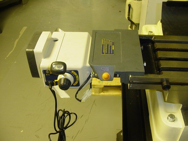 Quite a bit of overhang but looing at the other photos provided it may be possible to mount the unit vertical with a bit of adaption. Phil. |
| 08/12/2011 13:09:46 |
Glad you posted this, I am going to get one ordered, can be my xmas project to get it fitted. Rang Axminster about the unit, tech guy forwarded a picture, the ZX unit as they didn't have anything on the RF unit. Chester have got the power feeds on offer at the moment but they are still £100 more expensive. When I get the unit I will post details of how I got on fitting the unit. |
| Thread: VFD Drives |
| 02/06/2011 19:44:15 |
Hi Jon, Inverters and RCCD don't mix very well due to the noise suppression filter in the drive. If you must use an RCCD with the drive you will most likely need one that is designed to work with both AC and DC currents. These tend to be very expensive. You will also need to check the leakage current of the drive as this is usually quite close to he tripping current of the RCCD. From experience the RCCD usually trips when the drive is delivering a high current or when slowing down. In the past a badly earthed drive has destroyed the serial port of my laptop (back in the early days) when trying to configure it. Does your RCCD just power the inverter or the whole workshop? If there is a lot of electronic equipment powered up at the same this can increase the problem due to the filters built into the power supplies. It is possible to test the tripping current of the RCCD if you access to the correct test equipment. If you do the test with everything running in its normal condition safely and perform the test it will give you a tripping current. This current should be 30mA give or take a mA or so. If the tripping current is low then something on the supply is causing a lot of leakage and is a case of disconnecting one item at time and repeating the test until the offending item. It could be a combination of items added together causing. The inverter will be a big source. Damp can also be a cause of leakage current. If coolant gets where it shouldn't then this won't help things. |
| Thread: Forward reverse switch diagram |
| 29/05/2011 20:02:26 |
The part numbers are usually arranged: family number, switch pattern, operator code. Be aware though that they do both standard and custom switch patterns. Fun when you take one to bits - springs go everywhere. The A213 looks like the switching pattern code. They seem to use the same switching code for all the different ranges. Catalogues are available to download and do show the switching pattern but can take a bit of understanding to decode. |
| Thread: DRO,s fo Mini Lathes. |
| 20/05/2011 20:54:47 |
My brother got these dials for his C3 super. They are a bit picky about which batteries are used with them - don't use cheap 'equivalents'. They're ok as a guide but for anything accurate handheld digital verniers are much better. They were a bit of a sod to fit to his machine and should be treat as a kit of bits to finish. Only good thing about them is the ability to switch between metric and imperial at the press of a button - he's metric era, drawings are imperial, bit of square peg round hole. |
| Thread: Altivar 28 Inverter |
| 17/05/2011 21:25:58 |
Any chance of posting a drawings of the electrical wiring. Modern inverters usually have lots of options and some of the newer ones have an Emergency Stop feature built in that must be wired/configured correctly. Not played with Altivar for quite a while, some drives have config macros that allow the basic settings to be configured relatively easily. Usually things like voltage, current, power factor, rated speed, etc. Big question is, why did the old unit go bang? Inverters are one of those items that you must read the manual, not just the 4 page flyer usually labelled 'not quite' Getting Started. Altivar's use to come with a CD that has additional manuals on them, unless Group Schneider have decided to reduce costs further. The manuals can be downloaded from the Group Schneider website but can take a bit of finding. |
| Thread: VFD Drives |
| 17/05/2011 01:01:52 |
If your on a 3ph supply then a thing called power factor comes into effect. Electricity supplies get a bit funny as they don't like low power factors, or unbalanced usage on the supply. If you have a 3ph meter then the meter can measure the phase angle and adjust the usage reading. If you have 3 single phase meters then the supply company adjusts the readings for you. The other thing the suppliers don't like is heavy short duration loads normally referred to as peak demand and will usually bill you as though you were using this for the whole billing period. If all your workshop sockets are on one phase then this can easily trigger a premium billing period. Put kettle on one phase, compressor on another, etc. Just watch out for wiring regs as sockets on different phases have a minimum separation distance. If you have noise on inverters this is from my experience a very very very difficult mine field to navigate. General problem is bad earthing. Earth to drive must be very low resistance. Earth from drive to motor must be very low resistance. The cable from the drive to the motor must be a screened cable with an earth core. An 'SY' type cable is useful for this. The earthing must be connected to the drives earth connection. The screen must also be connected to this earth connection. The earth core at the motor end should be connected the motor earth terminal and the screen must be connected at the motor end. Best thing to use for this is an EMC gland. Expensive for what they are but worth it in the end. All paint must be removed before connecting the earth or screen. Lots of people don't bother and wonder why they have problems. Inverter control terminal, eg run, stop and speed should usually be cabled in a screened cable with the screen connected at one end only - the drive end. Ferrite cores can help reduce interference, but you need to be careful as these can get very hot if not used correctly. They act as filters and are usually rings or cores that you pass the wire through or clip around the cable, you need to refer to the drive manual for details but with the rings you usually pass the motor phase wires through them twice immediately after the cable leaves the drive. I have experienced situations where all the above has been done and still had noise problems and the only way to cure it was to disconnect the screen - just doesn't make sense - brick wall helps. Another thing that can cause excessive noise is the switching frequency the drive is using. On most of the modern drives this can be changed though a parameter but sometimes makes the situation worse. Don't fit any switches between the drive and motor as these will be destroyed quickly as the output from the drive is not a pure sin wave and most switch gear is designed to work only with a pure sin wave, especially the cheap far east import stuff. |
| Thread: This months MEW are 3 CNC features two too many |
| 17/05/2011 00:28:28 |
I agree with John, maybe MEW should be renamed Engineer's Workshop as most of the articles in it don't have much to do with models and from reading other posts on the forums, a lot of the post seem to be about things other than models. More, a how do I do..... Or, how about 'Weekend Engineer's Workshop' Any excuse to avoid SWMBO |
| 17/05/2011 00:22:52 |
CNC, love it or hate it, its here to stay even in the 'model' engineer's workshop. As an automation engineer designing control systems for various pieces of industrial equipment it is nice to see how the other side does things. Its 'so yesterday', everything is stepper control. No AC/DC brushless servo. No Linear motors. No hydraulic servo. No distributed servo networks. Nice simple steppers. I have only just got into the mechanical side of engineering, learning to use the lathe and milling machine to my apprentice trained employee's horror. MEW has been great at giving me insight into the basics, but to me at the moment a lump of metal is a lump of metal. How about an article or two on properties of metals, what each is used for, merits and failures under certain applications etc. I think an article something like this was proposed in another thread and was shouted down. We all want something different from the magazine. I do like the printouts of the 'G' code though, very retro!. Reminds me of my Vic20 days. From my experience though, 'G' code is very machine and implementation dependant as some of the codes are customised to perform specific functions on the machine. Printing 'G' code in the magazine is bit like the old computer days when the computer magazines used to print multiple versions of the same program for all the different computers out there, BBC 'A', BBC 'B', BBC Electron, C64, Spectrum, Amstrad, Dragon, Oric, Apple II, TRS80 etc. Maybe not 3 articles per issue. One or two now and then, but don't bother with the 'G' code. And please, we don't all have Myford lathes. What about articles for other makes and models. Ok, I know I can adapt the designs but it would be nice to know what other people out there are using. Ok, sorry, rant over. |
| Thread: Removing needle roller bearings ? |
| 04/05/2011 11:38:16 |
Had to go earn some pennys to keep SWMBO in the life style she hasn't become accustomed to. (Playing with a mattress spring assembly machine today). Will give your suggestions ago, but will probably be the weekend now. My personal favourite is Steve Garrnets idea, Maybe the simplest in the long run. |
| 04/05/2011 00:08:55 |
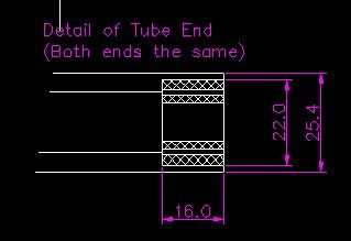 Hopefully this drawing pinched from some info about the machine will help. The hatched parts in the drawing are the two halves of the bearing housing and the needle rollers sit between them. |
| 03/05/2011 23:59:50 |
The tube is actually used as a roller with the outside surface needing to be a smooth unblemished finish. The overall diameter of the tube is 25mm (1" in old money - actual diameter not that critical but need to be parallel). There is a a needle roller bearing pressed into each end of this roller and the outer diameter of the bearing housing is 20mm.The bearings are on the inside of the tube. Through the centre of the tube is a 10mm shaft that has the inner bearing surface pushed onto each end and held in place with 'C'/'E'/'Cir' clips or something like (them things that get lost every time they ping off the shaft when you remove them). The tube/roller is about 300mm in length, it is basically thick walled tube turned parallel and machined to take the bearings at each end. The remaining wall thickness is about 2.5mm where the bearings are. The awkward thing is, is that the internal shoulder in the end of the tube is as deep as the thickness of the outer part of the bearing housing so I can't get anything on the inside side to pull the bearing housing out. The bearings used come apart easily into three parts, inner housing - 10mm internal diameter, the needle roller cage(missing on one end) and then the outer housing - 20mm outer diameter (stuck in end of tube). Apparently the idea in using needle roller bearings was to allow the outer tube part drift slightly on the inner mounting shaft - problem has arisen because the outer surface of the roller gets cleaned with some solvent (like Amberclean ME20 - that stuff shifts anything from everything) that has stripped the grease from the bearing, then put back together and run dry at high speed. The material the tube is made from is thick walled mild steel tube, so trying to collapse the bearing internally is most likely not possible unless is was cut somehow. I'm thinking, making him some new ones might be the best bet. |
| 03/05/2011 22:50:21 |
Ever wished you'd kept your mouth shut?. This is one of those 'You know how to fix things don't you - can you just have a look at.....' jobs. The problem: the needle roller bearings pressed into the ends of a tube have disintegrated and its anybodies guess where the needles have got to. The bearings are pressed into the ends of a tube up to a shoulder. Tube is 25mm OD, bearings are 20mm OD. Can't get bearing puller in, can't tap it out from other side. Can't heat tube as it will damage outer surface. Only thing I can think of is a small die grinder to cut through the outer bearing housing and then hopefully the housing can be encouraged to come out. If anybody has any better ideas on getting these damned fiddly things out. |
Magazine Locator
Want the latest issue of Model Engineer or Model Engineers' Workshop? Use our magazine locator links to find your nearest stockist!
Sign up to our Newsletter
Sign up to our newsletter and get a free digital issue.
You can unsubscribe at anytime. View our privacy policy at www.mortons.co.uk/privacy
Latest Forum Posts
- *Oct 2023: FORUM MIGRATION TIMELINE*
05/10/2023 07:57:11 - Making ER11 collet chuck
05/10/2023 07:56:24 - What did you do today? 2023
05/10/2023 07:25:01 - Orrery
05/10/2023 06:00:41 - Wera hand-tools
05/10/2023 05:47:07 - New member
05/10/2023 04:40:11 - Problems with external pot on at1 vfd
05/10/2023 00:06:32 - Drain plug
04/10/2023 23:36:17 - digi phase converter for 10 machines.....
04/10/2023 23:13:48 - Winter Storage Of Locomotives
04/10/2023 21:02:11 - More Latest Posts...
- View All Topics
Support Our Partners


Shopping Partners
Subscription Offer

Latest "For Sale" Ads
- Reeves** - Rebuilt Royal Scot by Martin Evans
by John Broughton
£300.00 - BRITANNIA 5" GAUGE James Perrier
by Jon Seabright 1
£2,500.00 - Drill Grinder - for restoration
by Nigel Graham 2
£0.00 - WARCO WM18 MILLING MACHINE
by Alex Chudley
£1,200.00 - MYFORD SUPER 7 LATHE
by Alex Chudley
£2,000.00 - More "For Sale" Ads...
Latest "Wanted" Ads
- D1-3 backplate
by Michael Horley
Price Not Specified - fixed steady for a Colchester bantam mark1 800
by George Jervis
Price Not Specified - lbsc pansy
by JACK SIDEBOTHAM
Price Not Specified - Pratt Burnerd multifit chuck key.
by Tim Riome
Price Not Specified - BANDSAW BLADE WELDER
by HUGH
Price Not Specified - More "Wanted" Ads...
Get In Touch!
Do you want to contact the Model Engineer and Model Engineers' Workshop team?
You can contact us by phone, mail or email about the magazines including becoming a contributor, submitting reader's letters or making queries about articles. You can also get in touch about this website, advertising or other general issues.
Click THIS LINK for full contact details.
For subscription issues please see THIS LINK.
Digital Back Issues


Donate

 Register
 Log-in
Model Engineer Magazine
- Percival Marshall
- M.E. History
- LittleLEC
- M.E. Clock

ME Workshop
- An Adcock
- & Shipley
- Horizontal
- Mill

Subscribe Now
- Great savings
- Delivered to your door

Pre-order your copy!
- Delivered to your doorstep!
- Free UK delivery!