Member postings for JasonB
Here is a list of all the postings JasonB has made in our forums. Click on a thread name to jump to the thread.
| Thread: UKCA and CE Marking of Boilers |
| 04/08/2023 10:00:38 |
Link to not having to use UKCA |
| 04/08/2023 09:10:20 |
I would expect the boiler makers revert to the CE mark as any other manufacturer will if it falls into one of the groups were CE will remain acceptable. Those that have also been selling to Europe have continued to CE mark those boilers and UKCA mark ones for the home market. Some even dual plate them so they can be used throughout europe and the UK. Quite a few UK boilermakers Edited By JasonB on 04/08/2023 09:26:16 |
| Thread: Why has my mild steel bent |
| 04/08/2023 09:04:49 |
Dell, which way did it bend? From your first post I assumed it had cupped, either opening or closing when you cut the tee slot in which case skimming all 4 sides would not have made much difference. It is not so much machining to release stresses but balancing the stresses on each side so a big slot cut in from one side will not be balanced hence cupping If it bent along it's length on the initial clean up then flipping it over so you take small amounts from each side in turn until down to finished size can help rather than doing one side then the other.
|
| 04/08/2023 06:57:12 |
Posted by Ramon Wilson on 03/08/2023 22:20:28:
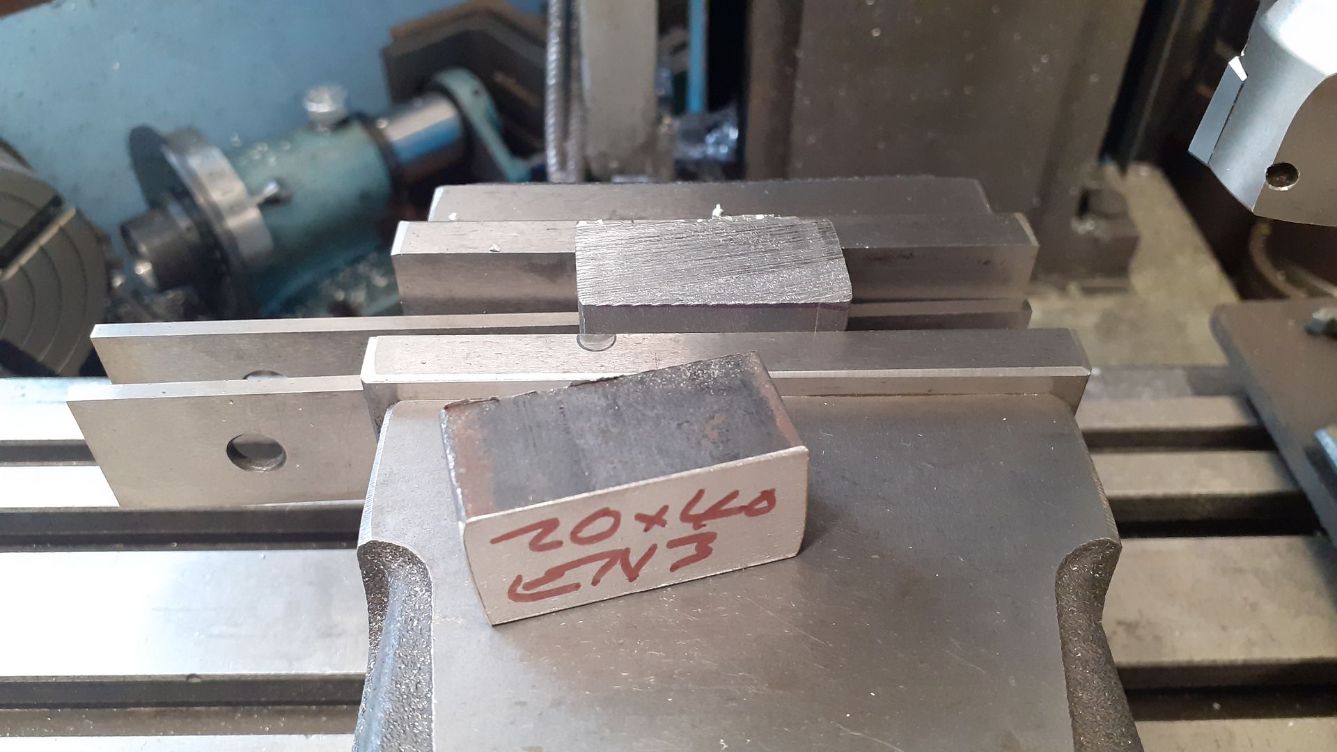
Why would you need to protect material from oxidising if you are annealing it in the first place to stress relieve it for machining all over? Tug It may be you just need to cut a notch out of one side like the OP's part machine a tee slot and don't want the part to cup as the slot closes up/opens out. Same reason bright bar is not good to use for loco frames as it moves when the cut outs for the axle horns are done. Heating larger sections will take some time and is likely to leave some scale on the surface which would need cleaning off in some way, protecting the unmachined surfaces would save having to do that My reason for initially mentioning that the surface would be affected by heating was to make anyone doing it aware that what started bright would not be after heating so they should bear that in mind either allowing for a skim to clean things up or a bit of draw filing if minimal. Also people tend to by bright as they want something to look bright so don't get the black, as heating will make it black they may as well just start of with black material provide dit can be had in the size spec they want. While on the subject for those who have not used it black bar and flat often has rounded edges or corners so if your part is tight on size you may want to buy larger Example some "black" 20x40 cut for crank webs
Edited By JasonB on 04/08/2023 07:07:06 |
| 03/08/2023 19:01:20 |
I have tried it with flux which worked, not tried the others but may well help. |
| Thread: Alyn RLE Last and First |
| 03/08/2023 18:55:38 |
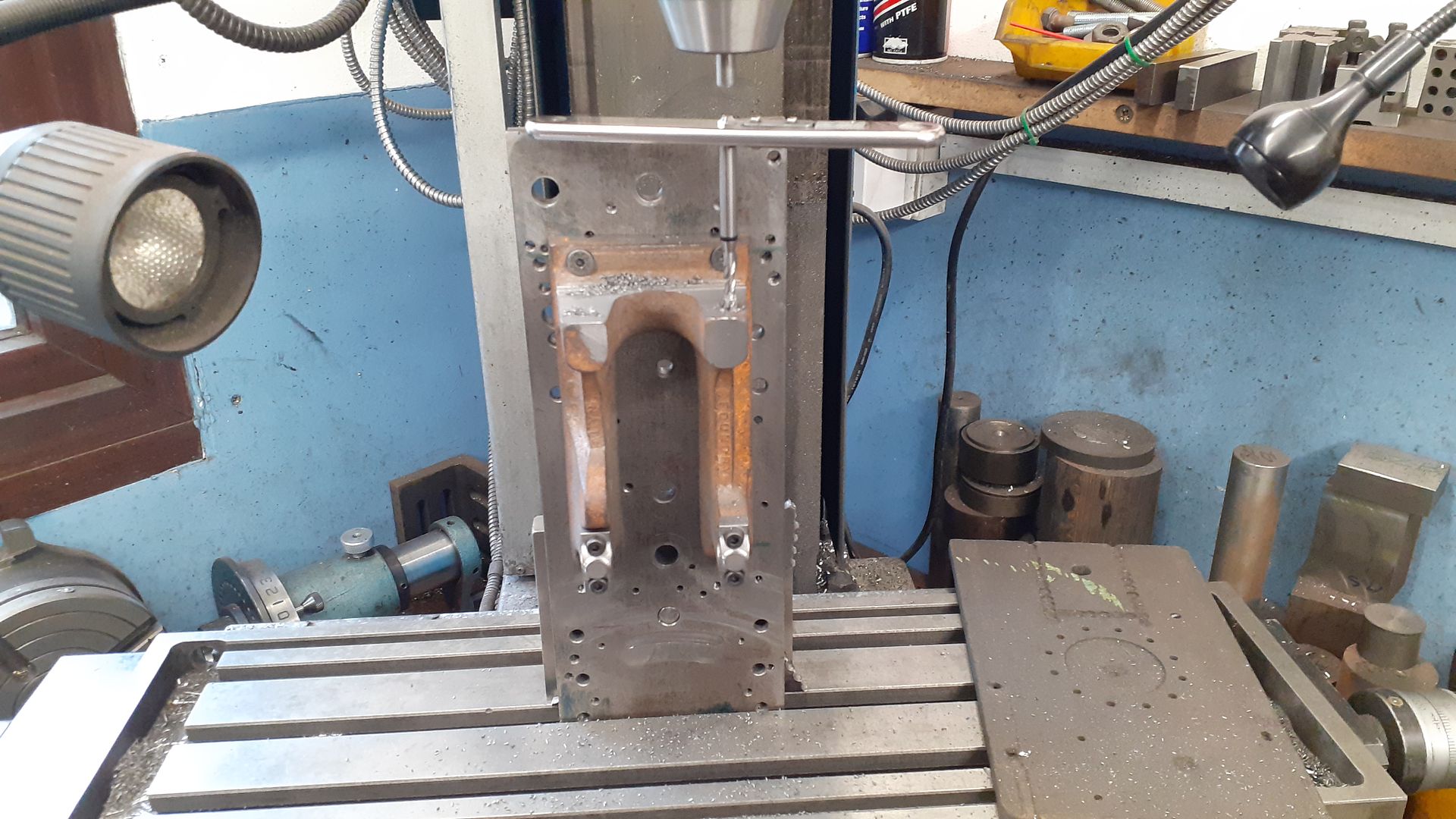
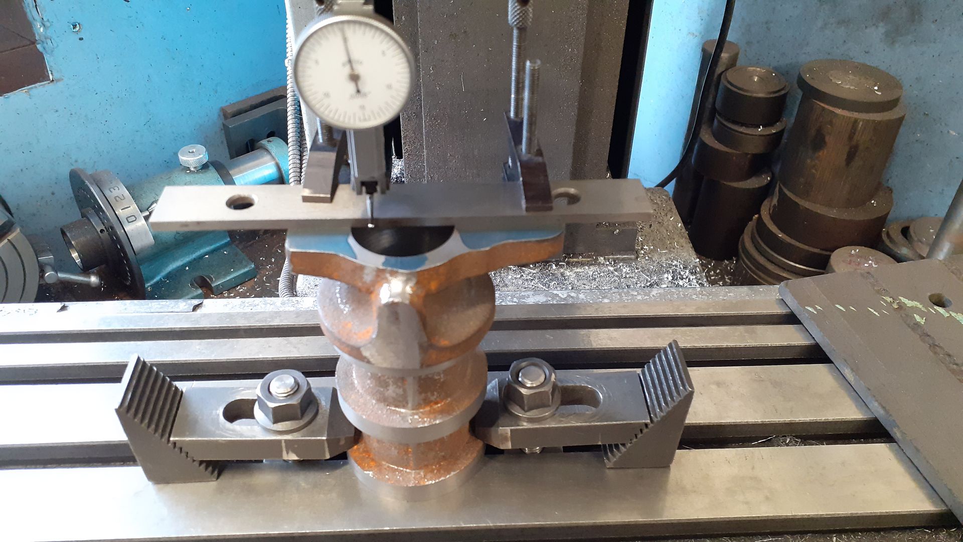
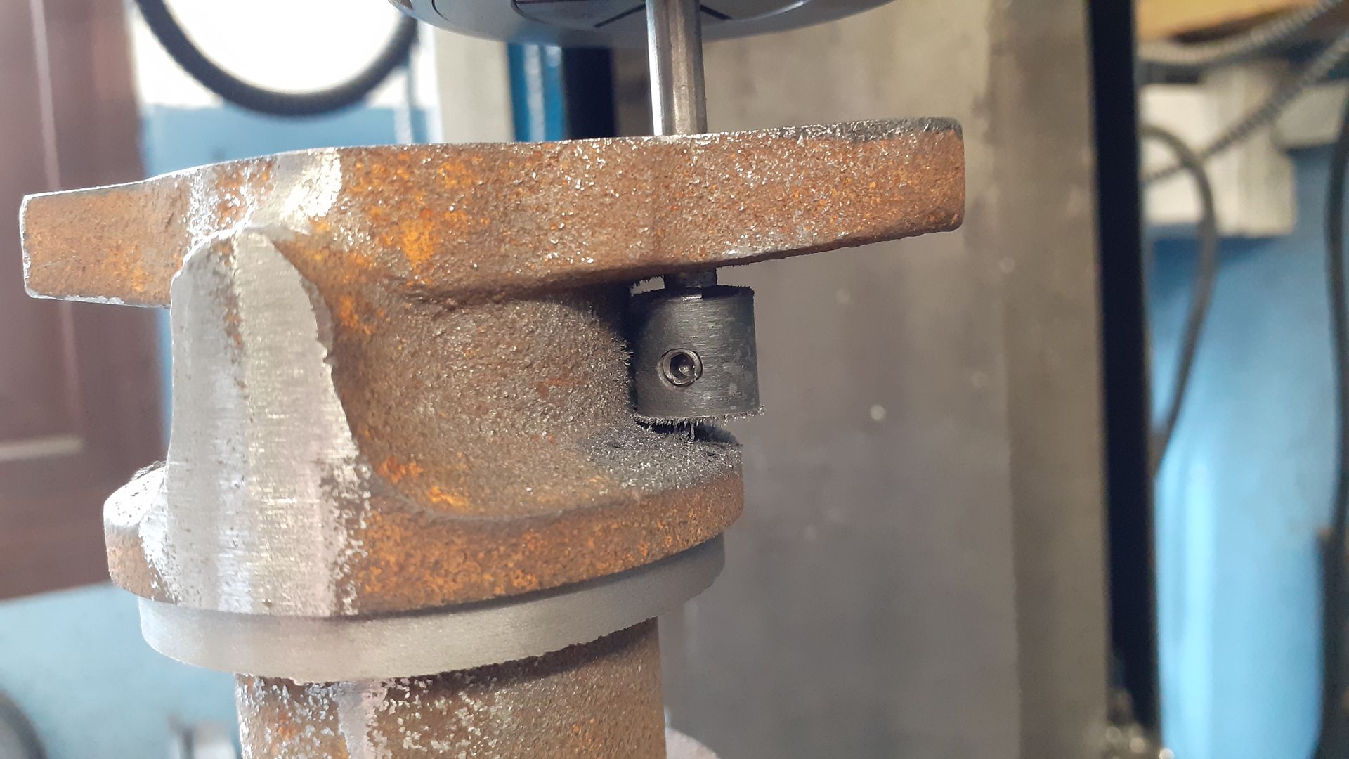
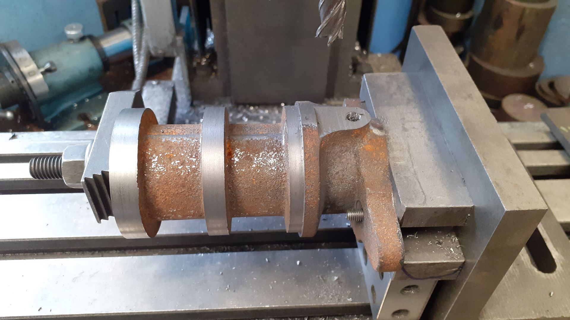
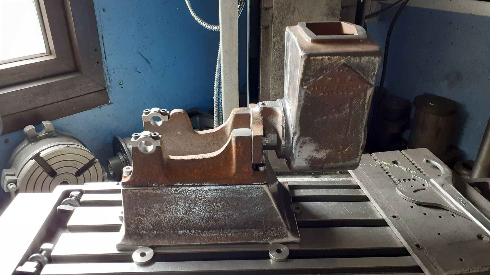
While the crankcase was still mounted to the machining plate I clocked it vertical on the mill, located ctr and cylinder height and then off set each side to drill and tap for the two studs to hold the cylinder in place |
| Thread: Why has my mild steel bent |
| 03/08/2023 18:26:34 |
As Bo'sun says it can happen with cold rolled (Bright) steel and other metals for that matter. The final cold rolling intriduces stresses into the metal and when you cut unevenly into it the stress will be released on one side but not the other. As your tee slot only cuts through one side there is not much hope of trying to balance the cuts by doing the same each side. Two options, start with hot rolled (black) material which will need a bit more work to get a clean surface or stress relieve bright by heating to red heat and allowing to cool slowly which will end up making the surface look like black bar |
| Thread: Stated thread depth never works for me. |
| 03/08/2023 08:57:29 |
As I said easy enough to work out how much more infeed is likely to be needed for partial form inserts that will get you quite close.
A quick look at an insert manufacturers catalogue gives the tip radii of full and partial forms. A full form 12tpi whit insert has a 0.012" radius (0.024dia) and stated infeed of 0.054" A G55 partial insert which covers 14-8tpi has a 0.0085" radius ( 0.017" dia) but no infeed given but from the above you can see it would need an infeed of 0.058" to get a similar flank measurement An AG55 Partial insert has a tip radius of 0.003" (.006dia) again no infeed but from image needs an infeed of 0.065" So depending on which partial form insert you have feed in to those numbers, thread may still seem a bit tight so a file running along the crests may be all that is needed to get it to fit. Flex in the machine, spring passes etc will all affect final fit so can't always just go by numbers
Edited By JasonB on 03/08/2023 08:59:16 |
| 03/08/2023 07:49:30 |
It does not reduce the OD. If you look at that first image I posted of the Whit thread form you should be able to see the crests of the threads are rounded not pointed but the top of those crests measure 1/2" This rounding of crests that the full form inserts give is a good indication that you have fed in the correct distance, if there is a flat you have not gone in enough if you keep feeding after the inserts starts reducing the OD you have fed in too far As for a get around you just need to measure with thread wires and note the infeed for a given tpi then next time you come to cut that same tpi you will know how deep to go. Or do the calculation, sketch in CAD etc as posted earlier |
| Thread: surface finish flycutter or shell mill on lathe? |
| 03/08/2023 07:10:37 |
Myford like you have should handle a square just over 3" without issue depends if there is much wear in the old girl. I've certainly flycut on all my lathes in the past, don't think I have tried a face mill but if I did would use the sharper inserts meant for non ferrous metal to lessen the load. You also need to consider how you would hold the block onto a vertical slide to machine the two flat 3 x 3 faces same would apply to a faceplate so 4-jaw is the easy option, probably have to use the outside jaws. The sides would not be so hard to hold for fly/face cutting I'd clamp them down to the cross slide with some packing to bring them upto ctr height If you don't fancy any of that then clicksprings rubbing on a sheet of emery looks to give him a good finish. I doubt you would have enough cross slide travel to worry about the trailing cut if flycutting might even be a problem just doing one face but not sure how far towards you the cross slide will go and what it's travel is. Edited By JasonB on 03/08/2023 07:12:25 |
| Thread: Drawbar M16 to 3/8 Adapter HELP. |
| 03/08/2023 07:00:08 |
But sounds like uncle murphy (OP) has a lathe so could drill and tap first using the lathe. If headroom to clear the 15mm head of teh adaptor is an issue make a fluch one like Alan suggests but cut a slot in the end so it can be screwed in and you also have the option to screw it out again if needed. |
| Thread: surface finish flycutter or shell mill on lathe? |
| 02/08/2023 19:28:02 |
Is there any reason for not holding the part in the 4-jaw and just turning the six faces? |
| Thread: Stated thread depth never works for me. |
| 02/08/2023 19:08:51 |
Posted by Jim Gardner on 02/08/2023 17:44:42:
Thinking about it some more, it seems to me that depth of cut, is depth of cut regardless of full or partial profile inserts. Couple of image sthat may show why some depths of cut are more correct than others. Nothing to scale but just to show the differences First shows three 55 degree tools, on the left is what a partial would look like with a small radius, in the middle a simple vee form straight off the bench grinder and on the right a full form with the larger radius to suit it's particular pitch If we touch off on the side of the shaft and then infeed 3mm the width of the Vee at the edge of the bar varies, the two sides of the vee are the thread flanks.
If we now try and cut a thread with the middle pointed form and the right hand full form both to the same 4.337 pitch as the full form you can then see that the full form has gone in and cut the correct thread but the pointed form has not gone in enough and the crest is flat and measuring with thread wires wire would measure a larger value
Now if the infeed of the vee tool is increased from 3mm to 4.116mm so that the flank distance becomes the same as the full form
You will then get a thread form that has the correct flank distance and if measured by wires would equal the 3mm infeed of the full form insert
|
| 02/08/2023 17:10:35 |
A lot of people make the famale part first and then cut the male to fit. Trial and error measuring with thread wires as you cut deeper will get the flanks right if you don't have a female part. Your insert may give a tpi range, it will have the radius for the smallest pitch in that range, a fag packet sketch or better still a CAD sketch will probably be the easiest way to work out how much deeper you need to go Edit partial are used bymodel engineers etc who don't want to spend out on a whole range of specific tpi insert. They will cut a specific range say 16-12tpi or 12-8tpi and work out cheaper if you are only doing the odd thread
Edited By JasonB on 02/08/2023 17:13:08 |
| Thread: UK Made Boilers |
| 02/08/2023 17:06:23 |
I believe the stamp on the boiler plate I showed is one of BES's |
| Thread: Stated thread depth never works for me. |
| 02/08/2023 17:03:11 |
Jim is that a full form or partial generic 55deg insert, only full form will work to the dimenson |
| 02/08/2023 17:02:10 |
Pic of why a pointed tool (green) or one with incorrect radius when fed in the set dimension doe snot reach the flanks of the thread
|
| 02/08/2023 16:56:27 |
Most likely your cutting tool does not have the correct radius ground on the end so to compensate for that you need to have a deeper infeed so that the flanks end up in the correct position |
| Thread: I like a nice tool but.. |
| 02/08/2023 13:22:11 |
I've got one of those, handy for when you plug holes, also quite a flexible blade so you don't scrape your knuckles |
| 02/08/2023 11:40:45 |
I don't see why a 360deg is needed unless you want to go down one side, along the bottom an dthen up the other all with a shallow blade that will wander. jap saw does the vertical cuts (board held vertically) then coping saw can simply be tilted to horizontal to cut out the waste upto the limit of it's throat. If you have awider board then rotating blade to 45deg is about right so you can saw horizontally without the frame hitting the work. Like wot the man says |


Magazine Locator
Want the latest issue of Model Engineer or Model Engineers' Workshop? Use our magazine locator links to find your nearest stockist!
Sign up to our Newsletter
Sign up to our newsletter and get a free digital issue.
You can unsubscribe at anytime. View our privacy policy at www.mortons.co.uk/privacy
Latest Forum Posts
- *Oct 2023: FORUM MIGRATION TIMELINE*
05/10/2023 07:57:11 - Making ER11 collet chuck
05/10/2023 07:56:24 - What did you do today? 2023
05/10/2023 07:25:01 - Orrery
05/10/2023 06:00:41 - Wera hand-tools
05/10/2023 05:47:07 - New member
05/10/2023 04:40:11 - Problems with external pot on at1 vfd
05/10/2023 00:06:32 - Drain plug
04/10/2023 23:36:17 - digi phase converter for 10 machines.....
04/10/2023 23:13:48 - Winter Storage Of Locomotives
04/10/2023 21:02:11 - More Latest Posts...
- View All Topics
Support Our Partners


Shopping Partners
Subscription Offer

Latest "For Sale" Ads
- Reeves** - Rebuilt Royal Scot by Martin Evans
by John Broughton
£300.00 - BRITANNIA 5" GAUGE James Perrier
by Jon Seabright 1
£2,500.00 - Drill Grinder - for restoration
by Nigel Graham 2
£0.00 - WARCO WM18 MILLING MACHINE
by Alex Chudley
£1,200.00 - MYFORD SUPER 7 LATHE
by Alex Chudley
£2,000.00 - More "For Sale" Ads...
Latest "Wanted" Ads
- D1-3 backplate
by Michael Horley
Price Not Specified - fixed steady for a Colchester bantam mark1 800
by George Jervis
Price Not Specified - lbsc pansy
by JACK SIDEBOTHAM
Price Not Specified - Pratt Burnerd multifit chuck key.
by Tim Riome
Price Not Specified - BANDSAW BLADE WELDER
by HUGH
Price Not Specified - More "Wanted" Ads...
Get In Touch!
Do you want to contact the Model Engineer and Model Engineers' Workshop team?
You can contact us by phone, mail or email about the magazines including becoming a contributor, submitting reader's letters or making queries about articles. You can also get in touch about this website, advertising or other general issues.
Click THIS LINK for full contact details.
For subscription issues please see THIS LINK.
Digital Back Issues


Donate

 Register
 Log-in
Model Engineer Magazine
- Percival Marshall
- M.E. History
- LittleLEC
- M.E. Clock

ME Workshop
- An Adcock
- & Shipley
- Horizontal
- Mill

Subscribe Now
- Great savings
- Delivered to your door

Pre-order your copy!
- Delivered to your doorstep!
- Free UK delivery!