Member postings for JasonB
Here is a list of all the postings JasonB has made in our forums. Click on a thread name to jump to the thread.
| Thread: Northumberland locomotive additional dimension |
| 13/08/2009 07:20:30 |
As I have said before I feel it would be best to put a thread at the beginning of the Northumbrian Topic that is a " Sticky" This means it will always stay at the top and not risk getting rolled over onto a second page. It can be tilted "Errors & Omissions"
Also this thread should only be accessable to the Mods' so it does not get filled with discussions about errors/ommisions, these can be done as they have been upto now and once resolved added to the sticky.
David if you are not sure what I mean, PM me and I'll explain again.
Jason |
| 11/08/2009 14:09:25 |
I think trying to stretch the existing frames will risk distortion or missalignment, maybe OK for someone with lots of experience but I would not suggest some of the beginners who are making the loco try it. If they have only done say a stuart before its likely they have never silver soldered and would not have brazing equipment.
Looking back through ME there have always been the odd errors that have slipped through, The big advantage of this forum is that they have been spotted and rectified in a far shorter space of time than the old letters apearing in postbag and waiting for the revisions to be included in a longer lead in time.
I know its upsetting for builders but this is a new design and some errors are likely, I know one of the posters in this thread has found a number of errors in the drawings of his current Traction Engine model and that design has been around far longer than Northumbrian.
I think you have sorted this situation out as quickly as you possibley could, (even posting at weekends when I'm sure you don't get paid for) and have put into action further steps to try and ensure it won't happen again.
Jason Edited By JasonB on 11/08/2009 14:10:52 |
| 10/08/2009 17:01:09 |
Thanks David
Thats what I suspected and I think your course of action will be the best in the long run although upsetting for those who have cut metal already. Better to buy new frames now than risk something more costly like a boiler being too long!!
Would it be possible to upload the revised drawing to this site, that way it will save people with net access having to wait for another six weeks for the revised one to come out. Robin has it on CAD and I'm sure could soon add the revised length an the two details above, if he's agreeable this could be added as a jpeg for all to see.
Jason Edited By JasonB on 10/08/2009 17:17:22 |
| 10/08/2009 07:29:36 |
"Drawing was modified for dimension but not redrawn so that is why it is not to scale."
So the proportions of the drawing are based on 2 1/8", 3/4", 2 1/4" and 1 5/8" between the axles.
The lines were not altered but the position of part 6 was moved forward and its dimension altered to 9/16 (after the frames had been cut?)
So if one dimension was reduced Another must have increased which would seem to be the 2 1/4 one
If your post above is to be followed can you confirm that the bolt holes are as per this sketch and several other peoples layouts and not as the drawing visually shows or as Pauls engine.
Jason
PS still waiting for length of firebox support and vertical position of rear horn rivits, can't assume these positions now as the drawing and photos cannot be used as a guide.
|
| Thread: Model Engine Builder |
| 09/08/2009 18:22:22 |
I've subscribed since it started and its a good mag. The last few issues they have started to include steam engines but the earlier ones were all IC
Where there has been an error on a drawing they have e-mailed pdf files of any revisions to all subscribers within a couple of days, not that there are many errors in their drawings. They will also e-mail when the mag is sent out so you know when its due as in the past publication dates were a bit elastic but that seems sorted now
Jason |
| Thread: Northumberland locomotive additional dimension |
| 09/08/2009 13:21:51 |
This still does not explain why the cylinder holes come out further back than the drawing or photos show, when its laid out using the sizes on the drawing.
When the 3/4" dim was reduced to 9/16 was the 2 1/4" dim increased by 3/16"? Propoirtionally it still looks to be 2 1/4". Can you get a size for the axle centers as this will act as a check for the intermediate sizes. Thats a measured distance not obtained by just adding up whats on teh ME published drawings. The Springbok drawings with the current issue are laid out a lot better they have overall length and axle centers along the bottom and other items along the top.
Jason
Edited By JasonB on 09/08/2009 13:26:30 Edited By JasonB on 09/08/2009 13:33:10 |
| Thread: Norton Manx model engine |
| 08/08/2009 17:52:16 |
You will need to alter one of those figures as the capacity decreases to the cube root of the scale. Not sure of the exact spec of the engine but
80mm bore x 100mm stroke gives approx 500cc
1/5th scale = 16mm bore x 20mm stroke gives approx 4cc
3/5th scale = 48mm bore x 60mm stroke gives approx 108cc
I think that most of his models are half full size which would give 62..8cc
Jason
Edited By JasonB on 08/08/2009 18:20:40 Edited By JasonB on 08/08/2009 18:23:24 |
| Thread: Northumberland locomotive additional dimension |
| 08/08/2009 13:21:31 |
Well the latest issue dropped on the mat this morning and its good to see that the first batch of errata have been covered in print. One thing to bear in mind though is that some people will be buying alternate issues with just the relevant articles in so may miss corrections that are not included with the build series.
Could I suggest a "sticky" thread at the top of the Northumbrian section that can contain all the corrections that can just be accessed by David and Richmond. That way they will not be scattered all over the forum and mixed in with comments. A link to this thread at the end of each build article would also be helpful by directing potential builders to the latest revisions.
"Another point you may not be aware of is that not all designs have been "proof tested" by people other than the designer at the time of publication. Even the best designs can have faults and drawing errors which do not come to light until people actually build one themselves."
Quite a bit of weight has been given to the fact that two further engines have been built to this design (though probably from the original drawings not ME published ones) so that point does not really stand here.
Jason
PS on the subject of the latest issue the home page is once again a month out of date, this should really be a regular fortnightly job for the person with access to that part of the site. |
| Thread: Northumbrian First Project |
| 08/08/2009 10:39:16 |
The actual position of the cylinder is probably not that critical so long as the 6" dimension is retained.
BUT
The 9/16" vs 3/4" anomoly will have far greater implications
1 The overal frame length is wrong
2 the position of the 1/4" for the valve gear will be 3/16 further from the valve chest and throw all the linkages out
3 exhaust pipes will be too short/long?
4 Boiler will be too long and affect many parts
5 Grate and firebox will be in wrong position
etc etc.
If the 9/16" does turn out to be wrong then there are really two options either scrap the frames and start again or alter all subsequent parts and drawings to suit but this option will be a suck it and see method as no engine has been build to the reduced length and its likely changes will be missed.
I know it does not help you Chris but my original advice when you said you were going to do this project was to give it a few month to see how the series progressed before making a start, looks like it was better advise than I thought.
Jason |
| Thread: Norton Manx model engine |
| 07/08/2009 19:09:28 |
The builder has done several classic motorcycle engines, they are all machined from solid without the use of CNC. I like his Matchless G45 the best.
I'm not sure if he uses works drawings or has access to the original engines to measure. He usually has at least one engine running at the Guildford rallys.
Jason |
| Thread: Shed insulation |
| 07/08/2009 17:01:02 |
I filled between the studs with 50mm celotex/kingspan type insulation then clad teh inside with 12mm chipboard as I got it for nothing but 12mm ply would do.
I have a small convector heater with a built in frost stat to keep the chill off at night, saves any metal getting too cold and the moisture from your breath or cutting fluid steam condensing on the cold surfaces.
Jason |
| Thread: Northumbrian First Project |
| 07/08/2009 16:52:17 |
I mentioned the firebox support length in the footplate thread. The holes are also not drawn to scale/preoportion, 1/8 is shown larger than the 6BA but thats nit picking
 There rear horn holes are shown different on the frame drawing to the layout on the horn drawing, one has the top holes above the 1" cut out, the other below
 How do your hole sline up on the CAD drawing, any chance of attaching it so we can have a look.
Would be nice to get an answer Today as I'm sure some builders are holding off cutting any more metal until these issues are resolved and would have liked to spend the weekend in teh workshop
Jason Edited By JasonB on 07/08/2009 16:55:31 |
| Thread: Northumbrian Coupling Fork |
| 06/08/2009 18:54:52 |
I see from Fig 14 on page 155 that the major dia for the threaded end of this part is given as 5/32"
Any beginners trying to thread this part will end up with rather little thread engagement as this is just about the tapping size for 2BA.
Turn this Dia down to 0.185" and then thread to 2BA.
Hopefully this can be published along with the other anomolies in the earliest possible issue.
Jason |
| Thread: Geared Head Oil |
| 06/08/2009 16:23:32 |
From another forum that I didn't have time too look at yesterday.
Try these people they do several weights of hydralic oil equal to Shell Tellus in small amounts
Jason |
| 05/08/2009 07:31:43 |
Most makers will list a suitable oil in the handbook, What lathe is it? Its usually a lightweight hydralic type oil.
If its a far eastern lathe then Warco sell suitable oil
Jason |
| Thread: Northumbrian Footplate mounting. |
| 05/08/2009 07:29:18 |
Thanks David
Although I am not building this loco (I became involved when another member pm'd me with a query) It seems a shame that a project aimed at beginners has so many errors/missing data.
This is likely to put new model engineers off rather than encourage them particularly as it looks like anyone who has made a start on their frames will have to scrap them as there is no easy way to add 3/16 to their length.
I hope that these revisions will be published in ME ASAP to prevent anyone without net access from making thes eerrors.
Jason |
| Thread: Northumbrian First Project |
| 05/08/2009 07:22:42 |
Just in case anyone following this thread has not seen Davids reply in the "footplate" thread .
The 9/16" distance mid way along the frame should be 3/4" which means anyone who has started to cut or drill their frames will likely have to start again.
Jason |
| Thread: Northumbrian Footplate mounting. |
| 04/08/2009 17:56:30 |
Posted by David Clark 1 on 04/08/2009 17:07:16:
The cylinder pitch is 6inches to centreline and runout is 3/8 down.
I was asking about the cylinder in relation to the holes for item 10, see the last half dozen posts in the "first project" thread.
If drawn using the dimensions on the ME Drawing the six cylinder mounting holes come out further back than shown.
Can you confirm that the 9/16 dimension mid way along the top is correct as it is drawn far larger than the 9/16 bolt spacing and looks more like 3/4, if it were 3/4 this would put the cylinder fixing holes and holes for item 10 all in the right place.
Maybe the original drawings could be added to the articles section.
And while I'm on there does not seem to be any length given for the firebox support, it is just shown as a dotted outline on the frame drawing and the "1/8" clear locate from frame" note about the central hole is where the dimension should be.
Jason
Edited By JasonB on 04/08/2009 18:01:10 Edited By JasonB on 04/08/2009 18:03:46 |
| 04/08/2009 16:31:19 |
I think Chris is right the 2 3/8" is to where the plate narrows and the holes are shown at 1/4" back from this point which puts them in the wrong place. The whole plate is 2 1/2" front to back (2 3/8 + 1/8) so 2 1/2 less 3/8 (1/8 + 1/4) is 2 1/8". Its the holes that are on 1 7/8" cts not the ones near the edge.
I think you said that the drawings had been redrawn for the ME articles, so the ones that the author had checked may have been copies of his originals.
Jason
PS any news on the cylinder position query yet?
Edited By JasonB on 04/08/2009 16:33:09 Edited By JasonB on 04/08/2009 16:33:26 |
| Thread: Northumbrian First Project |
| 02/08/2009 07:33:32 |
Its 3 1/2 gauge
And there should not be a problem getting back issues, try the "Myhobbystore" link on the right.
Jason |
Magazine Locator
Want the latest issue of Model Engineer or Model Engineers' Workshop? Use our magazine locator links to find your nearest stockist!
Sign up to our Newsletter
Sign up to our newsletter and get a free digital issue.
You can unsubscribe at anytime. View our privacy policy at www.mortons.co.uk/privacy
Latest Forum Posts
- *Oct 2023: FORUM MIGRATION TIMELINE*
05/10/2023 07:57:11 - Making ER11 collet chuck
05/10/2023 07:56:24 - What did you do today? 2023
05/10/2023 07:25:01 - Orrery
05/10/2023 06:00:41 - Wera hand-tools
05/10/2023 05:47:07 - New member
05/10/2023 04:40:11 - Problems with external pot on at1 vfd
05/10/2023 00:06:32 - Drain plug
04/10/2023 23:36:17 - digi phase converter for 10 machines.....
04/10/2023 23:13:48 - Winter Storage Of Locomotives
04/10/2023 21:02:11 - More Latest Posts...
- View All Topics
Support Our Partners


Shopping Partners
Subscription Offer

Latest "For Sale" Ads
- Reeves** - Rebuilt Royal Scot by Martin Evans
by John Broughton
£300.00 - BRITANNIA 5" GAUGE James Perrier
by Jon Seabright 1
£2,500.00 - Drill Grinder - for restoration
by Nigel Graham 2
£0.00 - WARCO WM18 MILLING MACHINE
by Alex Chudley
£1,200.00 - MYFORD SUPER 7 LATHE
by Alex Chudley
£2,000.00 - More "For Sale" Ads...
Latest "Wanted" Ads
- D1-3 backplate
by Michael Horley
Price Not Specified - fixed steady for a Colchester bantam mark1 800
by George Jervis
Price Not Specified - lbsc pansy
by JACK SIDEBOTHAM
Price Not Specified - Pratt Burnerd multifit chuck key.
by Tim Riome
Price Not Specified - BANDSAW BLADE WELDER
by HUGH
Price Not Specified - More "Wanted" Ads...
Get In Touch!
Do you want to contact the Model Engineer and Model Engineers' Workshop team?
You can contact us by phone, mail or email about the magazines including becoming a contributor, submitting reader's letters or making queries about articles. You can also get in touch about this website, advertising or other general issues.
Click THIS LINK for full contact details.
For subscription issues please see THIS LINK.
Digital Back Issues


Donate

 Register
 Log-in
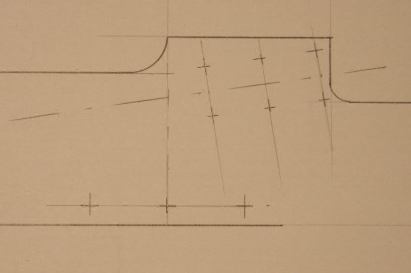
Model Engineer Magazine
- Percival Marshall
- M.E. History
- LittleLEC
- M.E. Clock

ME Workshop
- An Adcock
- & Shipley
- Horizontal
- Mill

Subscribe Now
- Great savings
- Delivered to your door

Pre-order your copy!
- Delivered to your doorstep!
- Free UK delivery!