Member postings for Max Francey
Here is a list of all the postings Max Francey has made in our forums. Click on a thread name to jump to the thread.
| Thread: Wiring Newman motor on Myford ML7 |
| 03/08/2017 08:52:44 |
Thanks Phil, got the PM. I was using two supplies one to posts 2 and 4 for run, the other, interchangeable in the chocolate block to the unmarked post and 3. So (in effect) 4 wires plus earth. Harry, yes I guessed that would be the case. You can actually hear the centrifugal switch drop back to the starting position as the speed winds down. That's with it on the bench, once back on the lathe probably won't be able to hear it. With the tumblers engaged, and the clasp nut engaged, the lathe actually stops fairly quickly, so I expect it will be difficult to throw the reversing lever fast enough to cause it to continue running in the same (wrong) direction, but I will hesitate at 0 to allow it to stop. M |
| 02/08/2017 17:33:26 |
Yes I agree, and will be putting a gland in. Given the lathe is fifty years old this year (I've had it for 5) and to be honest the motor looks older, I'm surprised the cable hadn't worn through. |
| 02/08/2017 16:14:12 |
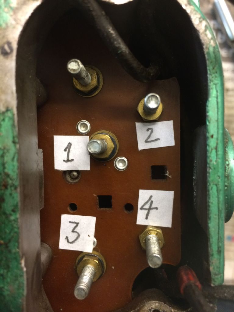
Thanks Gentlemen Your help has enabled me to proceed. I started as Phil suggested by removing wiring and labeling the posts as per photograph below. As David mentioned, the removable link between posts 2 and 4 would not be required for reversing operation, so I took it out:
At this stage I didn't bother to number the top left post as I established it had no connection and therefore apparently no function. I measured resistances between all the posts and discovered all were open circuit save for posts 1 to 3, which went closed circuit when the centrifugal switch was in the start position. I measured the resistances between wires corresponding to posts in the starting position, and got 16.5 Ohms between 1 and 2, and 6.6 Ohms between 3 and 4. I know the resistance of the starter winding should be greater than the running winding, so 1 to 2 is the starter, and 3 to 4 is the running winding. With this knowledge I was able to transcribe the circuit as Figure 1 below:
This is when I realised what the un-numbered post was for. I needed to be able to put the starting winding in series with the centrifugal switch. So, I rearranged the connections from the windings to the posts as per Figure 2 below:
To test this circuit, I lashed up a reversing switch arrangement using chocolate block connectors and tried it. It now works well and I can change the direction of the motor by reversing the polarity of the power connections at posts 1 and 3. Just need to wait for my reversing switch to arrive (I found one on eBay for about £9) and also the 4 core plus earth cable, then I can do the installation properly. Thanks again to everyone for their help and support. I maybe could've worked it out by myself, but it would have taken quite a few days! Cheers Max |
| 01/08/2017 14:40:14 |
Yes that's exactly it, because the leadscrew has 8tpi, and most metric threads don't have an exact whole number of teeth per inch, the thread dial indicator doesn't guarantee that you rejoin the thread at the same point following disengagement of the leadscrew. Hence it is necessary to keep the leadscrew engaged. I find it hard work manually turning the lathe backward to the start point of the thread, to take successive cuts. |
| 01/08/2017 12:11:52 |
Yes thats what I expected, but there isn't one. |
| 01/08/2017 11:52:08 |
Hi all My ML7 has a Newman motor which runs from the single phase mains via a Mem Auto Memota direct on line (DOL) starter. The motor does not have a capacitor, so far as I can see, and only operates in one direction. I would like to be able to run the lathe backwards (mainly to help when cutting metric threads), by fitting a reversing switch (possibly of the Dewhurst drum type). Unfortunately, the terminals within the motor aren't marked. Can anyone tell me what the terminals are from the photograph?
|
| Thread: Myford VM-B mill |
| 06/04/2017 10:26:52 |
Conclusion then: The key does very little, and since the VM-B requires a strip down to fit a new one, its not worth bothering. Thanks for the inputs folks |
| 03/04/2017 15:16:25 |
I have the same issue with my Myford VM-B, and am just looking at replacing the grub screw which provides the register. I think the damage was caused when I inserted an R8 arbour for a slitting saw. The arbour was tight and fooled me into thinking the draw bar had properly seated it. When the saw touched the metal I was cutting, the arbour spun in the spindle. Fortunately the spindle still seems OK, but obviously the register is no longer there. It looks like removal of the oil seal will not allow proper access of the grub screw, so I would need to loosen the elastic stop nuts at the top of the upper roller bearing and lower the spindle 4mm or so to give access. I'm loathe to do this as I'm unsure of the process to pre-load the bearings. So, the question is, do I put up with lack of register (seems ok from the posts above), or do I plunge in and lower the spindle. What do folks think? |


Magazine Locator
Want the latest issue of Model Engineer or Model Engineers' Workshop? Use our magazine locator links to find your nearest stockist!
Sign up to our Newsletter
Sign up to our newsletter and get a free digital issue.
You can unsubscribe at anytime. View our privacy policy at www.mortons.co.uk/privacy
Latest Forum Posts
- hemingway ball turner
04/07/2025 14:40:26 - *Oct 2023: FORUM MIGRATION TIMELINE*
05/10/2023 07:57:11 - Making ER11 collet chuck
05/10/2023 07:56:24 - What did you do today? 2023
05/10/2023 07:25:01 - Orrery
05/10/2023 06:00:41 - Wera hand-tools
05/10/2023 05:47:07 - New member
05/10/2023 04:40:11 - Problems with external pot on at1 vfd
05/10/2023 00:06:32 - Drain plug
04/10/2023 23:36:17 - digi phase converter for 10 machines.....
04/10/2023 23:13:48 - More Latest Posts...
- View All Topics
Support Our Partners


Shopping Partners
Subscription Offer

Latest "For Sale" Ads
- Reeves** - Rebuilt Royal Scot by Martin Evans
by John Broughton
£300.00 - BRITANNIA 5" GAUGE James Perrier
by Jon Seabright 1
£2,500.00 - Drill Grinder - for restoration
by Nigel Graham 2
£0.00 - WARCO WM18 MILLING MACHINE
by Alex Chudley
£1,200.00 - MYFORD SUPER 7 LATHE
by Alex Chudley
£2,000.00 - More "For Sale" Ads...
Latest "Wanted" Ads
- D1-3 backplate
by Michael Horley
Price Not Specified - fixed steady for a Colchester bantam mark1 800
by George Jervis
Price Not Specified - lbsc pansy
by JACK SIDEBOTHAM
Price Not Specified - Pratt Burnerd multifit chuck key.
by Tim Riome
Price Not Specified - BANDSAW BLADE WELDER
by HUGH
Price Not Specified - More "Wanted" Ads...
Get In Touch!
Do you want to contact the Model Engineer and Model Engineers' Workshop team?
You can contact us by phone, mail or email about the magazines including becoming a contributor, submitting reader's letters or making queries about articles. You can also get in touch about this website, advertising or other general issues.
Click THIS LINK for full contact details.
For subscription issues please see THIS LINK.
Digital Back Issues


Donate

 Register
 Log-in
Model Engineer Magazine
- Percival Marshall
- M.E. History
- LittleLEC
- M.E. Clock

ME Workshop
- An Adcock
- & Shipley
- Horizontal
- Mill

Subscribe Now
- Great savings
- Delivered to your door

Pre-order your copy!
- Delivered to your doorstep!
- Free UK delivery!