Member postings for Paul Major
Here is a list of all the postings Paul Major has made in our forums. Click on a thread name to jump to the thread.
| Thread: Base for a new machine shop aka "shed"! |
| 19/02/2014 20:27:44 |
LOL, thanks guys. My workshop has run out of room for all my kit. We have a large shed subdivided into 4 compartments at the mo that needs re-roofing and some other work. Thinking I can use the shell and "re-purpose" the interior to make a serious 'shop for the machines, but it will still look like a "shed" Paul. |
| Thread: Restoring Beaver VBRP Mill |
| 18/02/2014 09:58:41 |
Thanks Russ |
| Thread: Base for a new machine shop aka "shed"! |
| 18/02/2014 09:57:17 |
Great replies, thanks guys. Fortunately the shed is in Kent not California, although we have had our own sink hole recently on the M2 Heaviest item is the Beaver mill, probs about 1250 kg's. Will look into what sort of mesh and concrete to use. Not thought of putting PVA in the mix, haven't heard of that before. Was going to put a polythene membrane under the concrete before I poured but if PVA would stop it dusting and oil sinking in that would be a bonus as it is a nightmare in my workshop! Planning on keeping the entrance reasonably low but building a removable low level ramp to aid with shifting stuff. Having seen how useful it is in my workshop also thinking about rigging up a rail/gantry inside for lifting heavy components if I can find some cheap RSJ. Might think about a sink, means I need to run in water though, hmmmmm, Keep the thoughts coming! Thanks, Paul. |
| 17/02/2014 22:40:58 |
Hiya, just making plans to convert/refurbish part of a shed I have and turn it into a proper area for the growing number of machine tools I seem to be collecting. I am thinking about pouring a concrete base over hardcore, just wondered if there were any recommendations or things to bear in mind when doing this. Plan is too mount the machines (mill, shaper and lathe) onto the floor either on adjustable feet or shimming and grouting. Picked up a Wyler clinometer as part of a job lot of items at an auction so figure that should help with the levelling. Cheers, Paul. |
| Thread: Restoring Beaver VBRP Mill |
| 17/02/2014 22:22:50 |
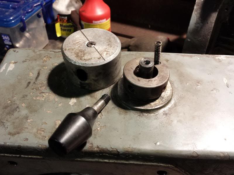
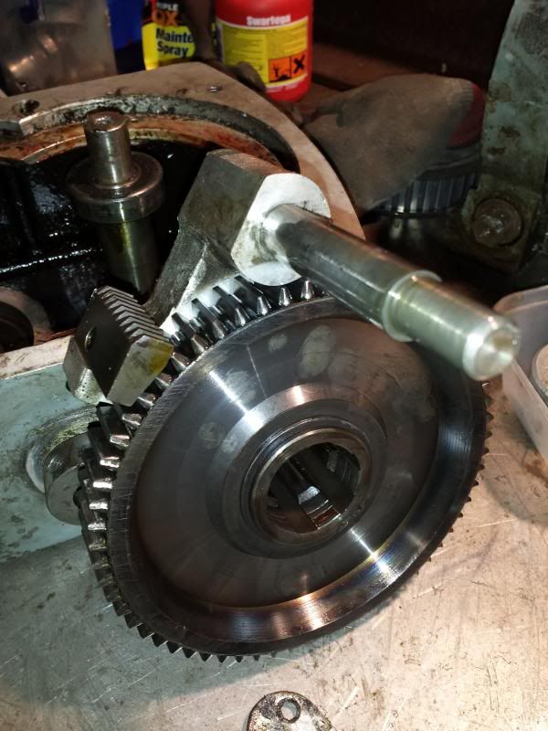
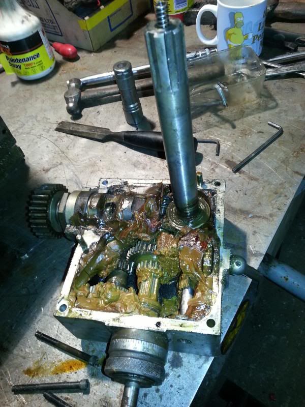
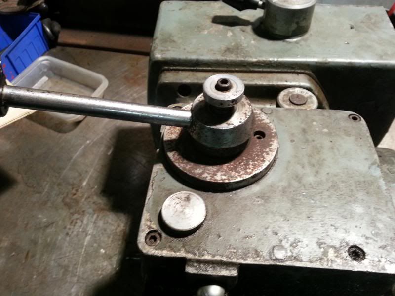
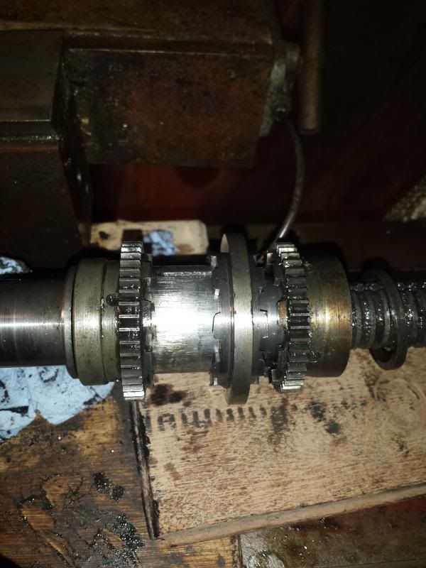
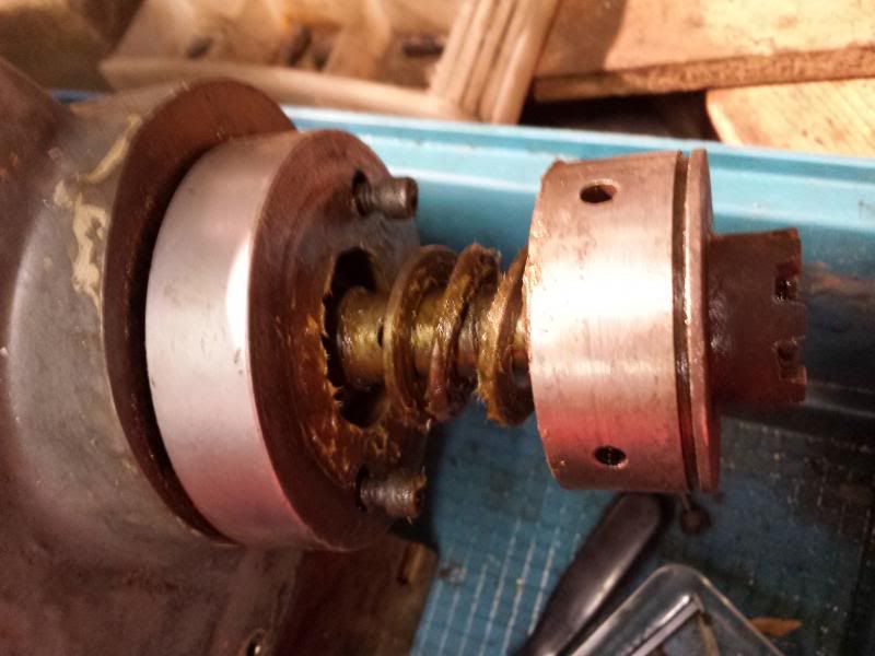
So, not sure if anyone is still reading this, can understand though - its probably not that rivetting just seeing something pulled apart Anyway, for posterities sake, started to dissassemble the gearbox which as well as transferring drive from the pulleys to the quill, also handles the backgear. First of removed the back gear lever, note spring that maintains the "detente" position on the lever,
The output shaft of the gearbox has a cog retained with a circlip. Circlip was removed and then a puller used on the gear revealing the woodruff key and rubber o-ring.
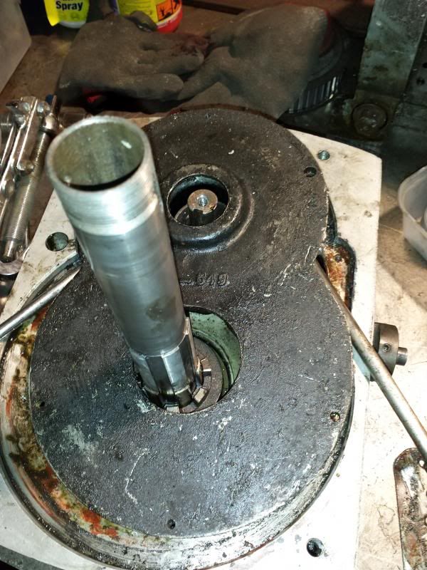
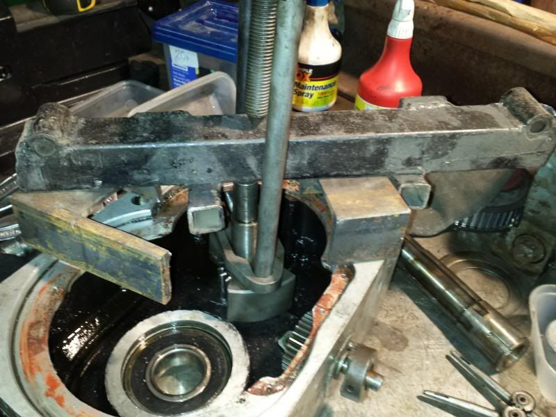
Flipped the 'box and attacked the top. The cover plate is held in by 4 screws but still wouldn't pop off. It turns out the backgear shaft has a bearing on the top end of the shaft which locates in the plate. To get the plate off you have to slide it off this bearing, but without anywhere to locate a puller its a bit of a job. Eventually levered it off.
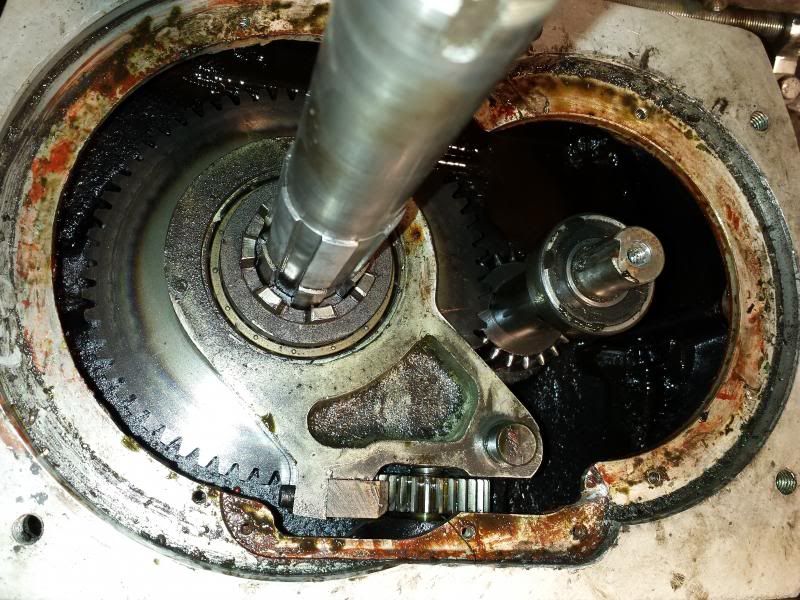
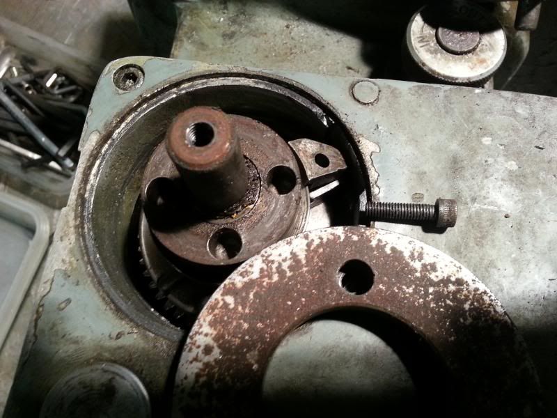
This is the insides of the gearbox, backgear shaft on the right and backgear selector hanging off the main shaft.
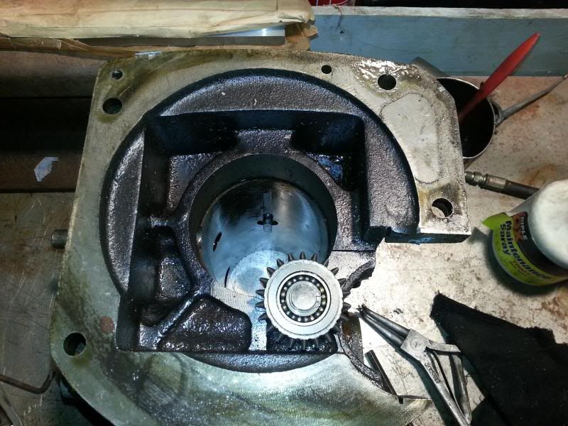
Backgear selector, wheel and clutch slid off the shaft
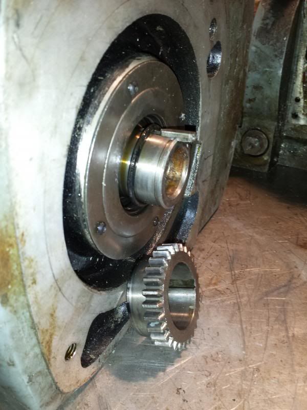
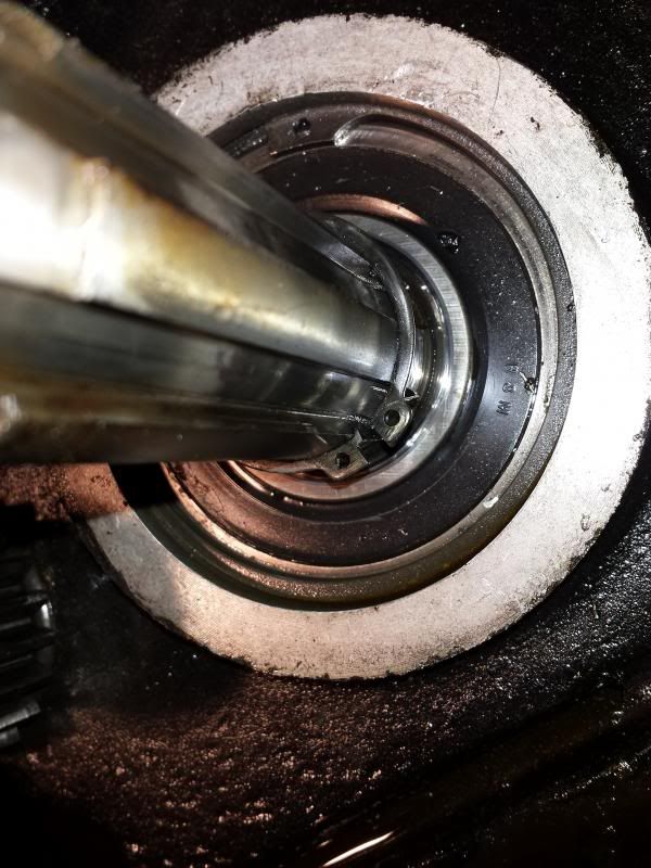
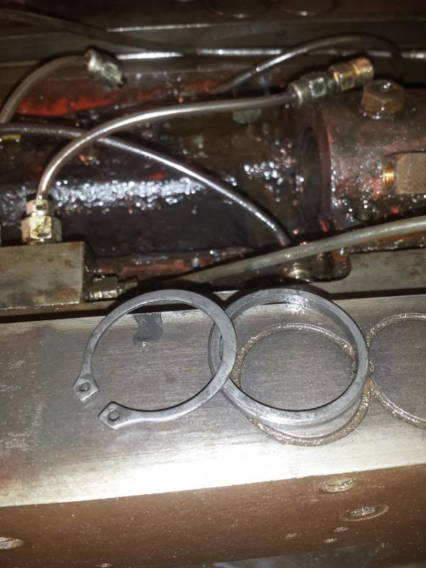
The shaft sits in a large bearing that sits in the bottom of the gearbox covered by a retaining plate on the underside and held in by the large circlip you can see in this picture.
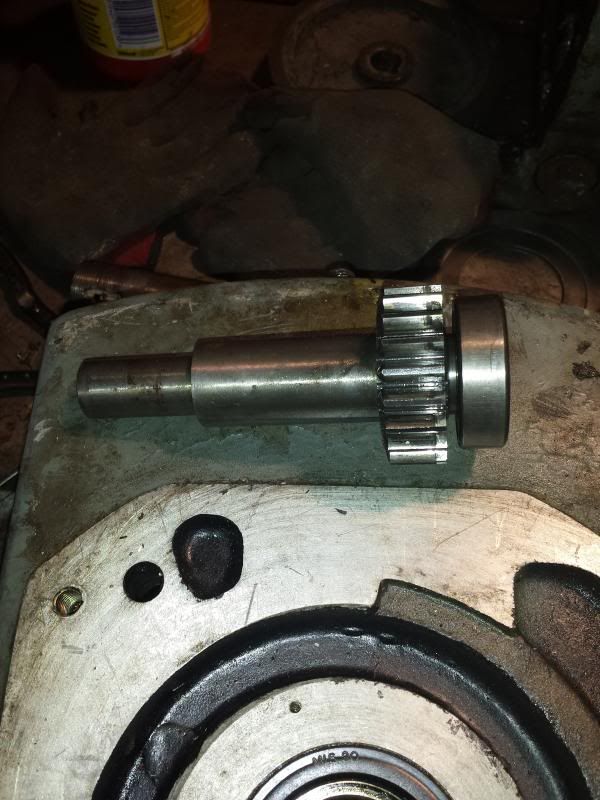
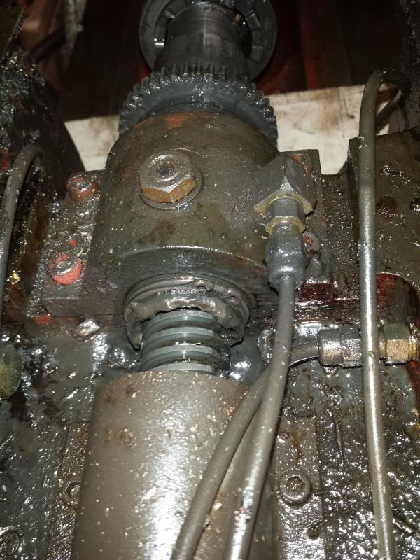
In the above picture you can also see a smaller circlip on the shaft itself, this is why the shaft cannot be withdrawn from the bottom of the gearbox and has to be removed via the procedure described above, i.e. from the top. With the main shaft out of the way I could then proceed to remove the backgear shaft. Some improvisation with another gear puller
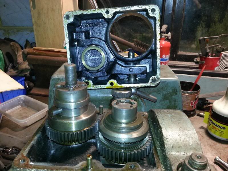
and the shaft complete with lower bearing comes out.
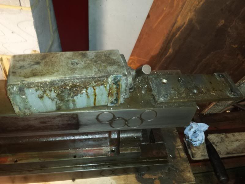
Next step, pressing out the main bearing and dropping the casing in the solvent tank, unfortunately I got a little bit distracted by purchasing and setting up this
Cheers, Paul.
Edited By Paul Major on 17/02/2014 22:26:41 |
| 09/02/2014 23:31:57 |
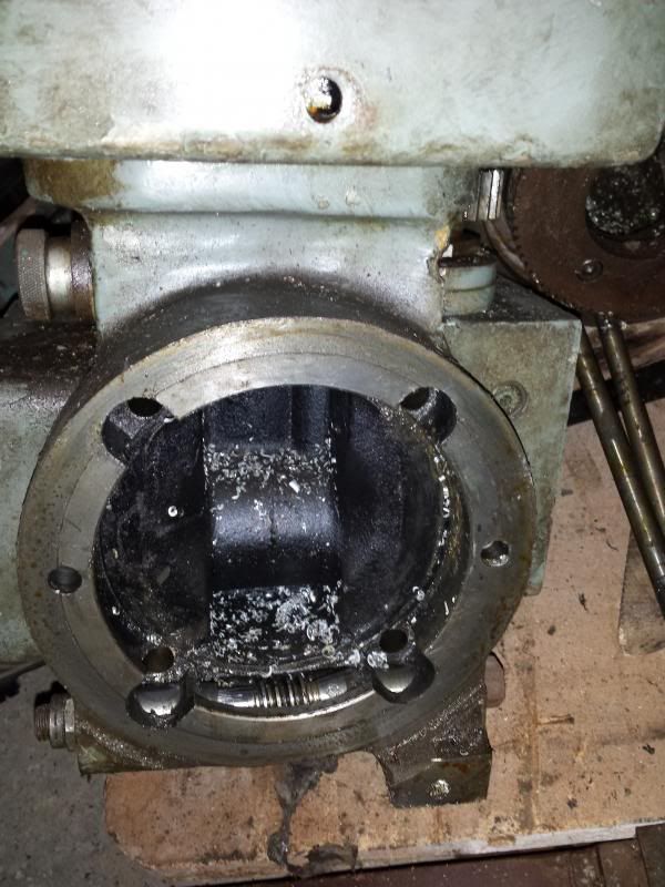
With the quill out the next part to remove was the feed gearbox.
Grease, grease and more grease View down the quill housing
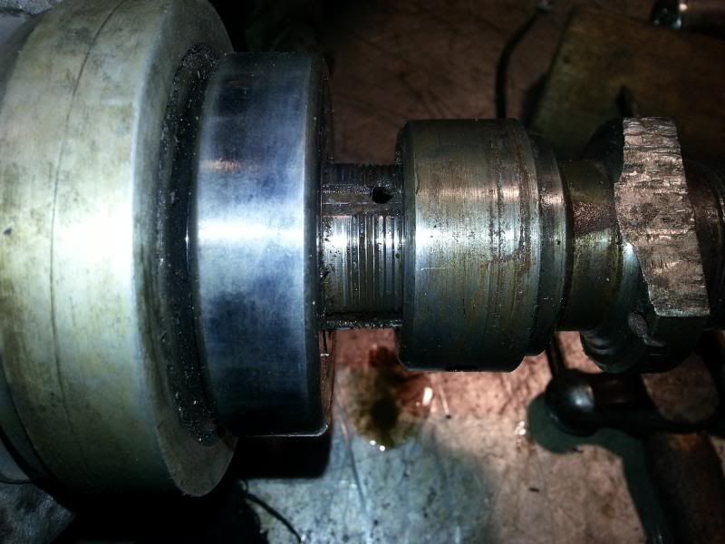
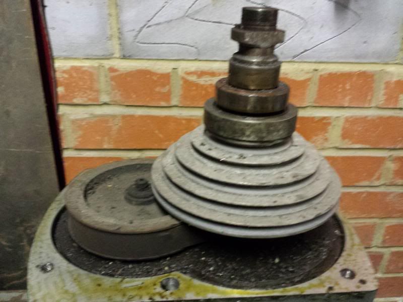
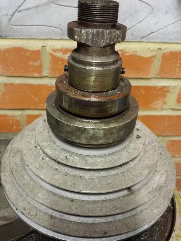
With the quill and gearbx outta the way I turned my attention back to the top part of the head. Remember the brake attachment on the top of the spindle that I couldn't get undone? Turns out it is screwed onto the spindle. With the quill removed I was able to lock the spindle and undo it.
and then pull the bearing off.
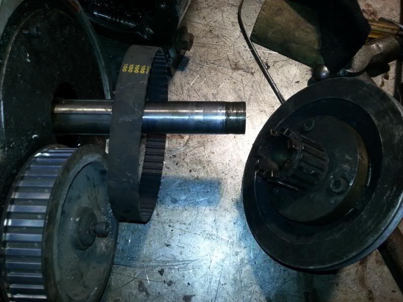
I was then able to pull off the top pulley and remove the toothed belt.
Next job was to try and get into the gearbox, easier said than done Cheers, Paul. |
| 09/02/2014 23:03:40 |
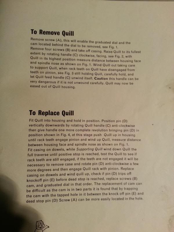
With the head off next job was to remove the quill. In answer to John's question last month the quill moves just under 5 1/2", which I guess makes it a 5" ?
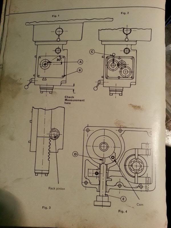
Removing the quill is about the only thing the manual gives instructions on so I will include it here incase it is of use!
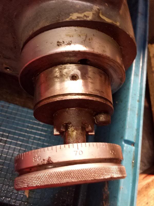
Setup for quill downfeed handle looks like this, mine is missing the micrometer dial
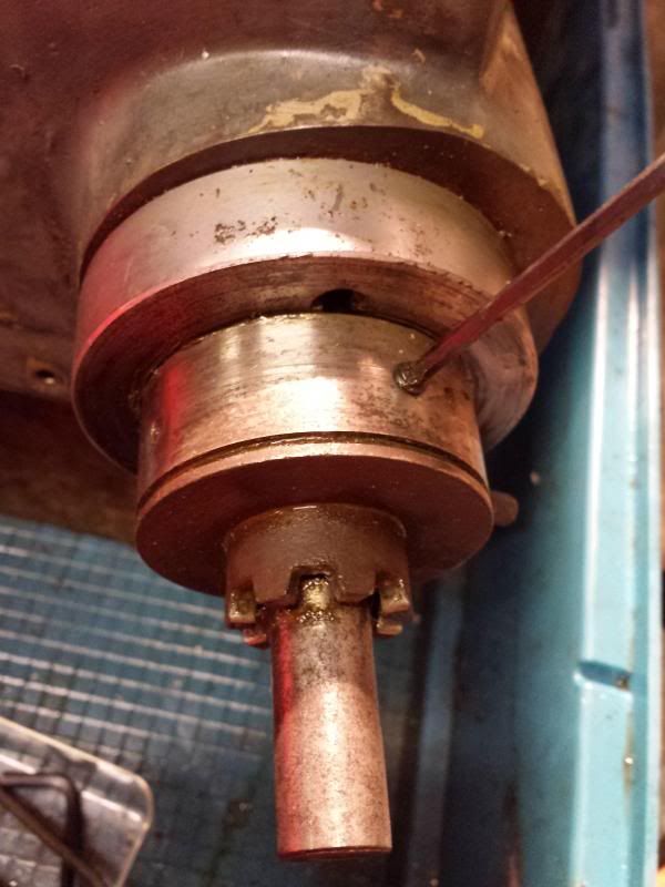
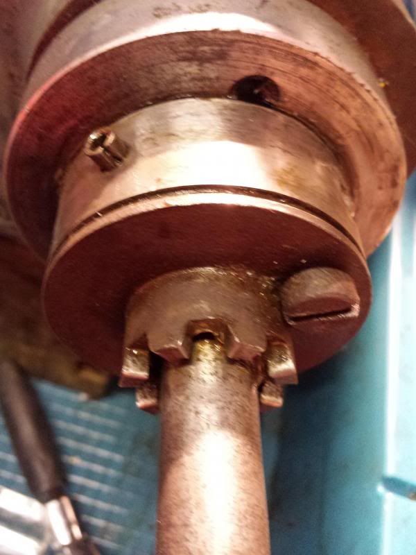
and removed shows the cam arrangement, (roughly 2 o'clock on the photo),
4 bolts undone and casing removed to show quill feed gears
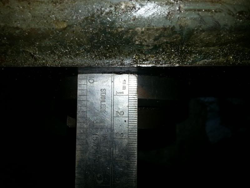
Quill protrusion measured,used when refitting quill,
then unwind the quill feed handle and the quill drops out of the head. Doesn't look in bad condition, couple of wear marks but no real grooves.
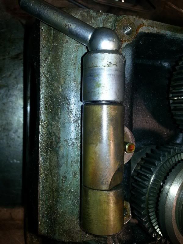
This is the locking pin for the quill
Cheers, Paul.
Edited By Paul Major on 09/02/2014 23:04:34 |
| 26/01/2014 14:02:46 |
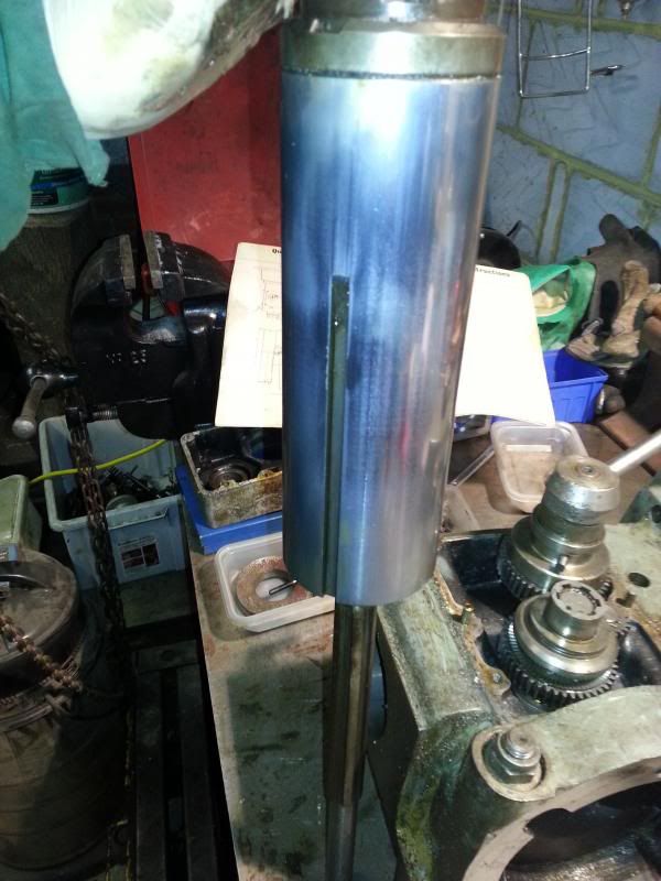
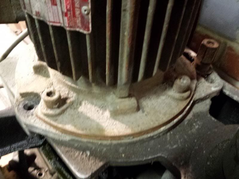
Got bored with cleaning so decided to strip down the head. This unit has a thumping great 2 speed electric motor sitting ontop of the 8 speed belt system. Not sure yet how many speeds that gives but it seemes a lot The motor is held in situ by 3 bolts and is on a moveable plate to allow for tensioning of the belts.
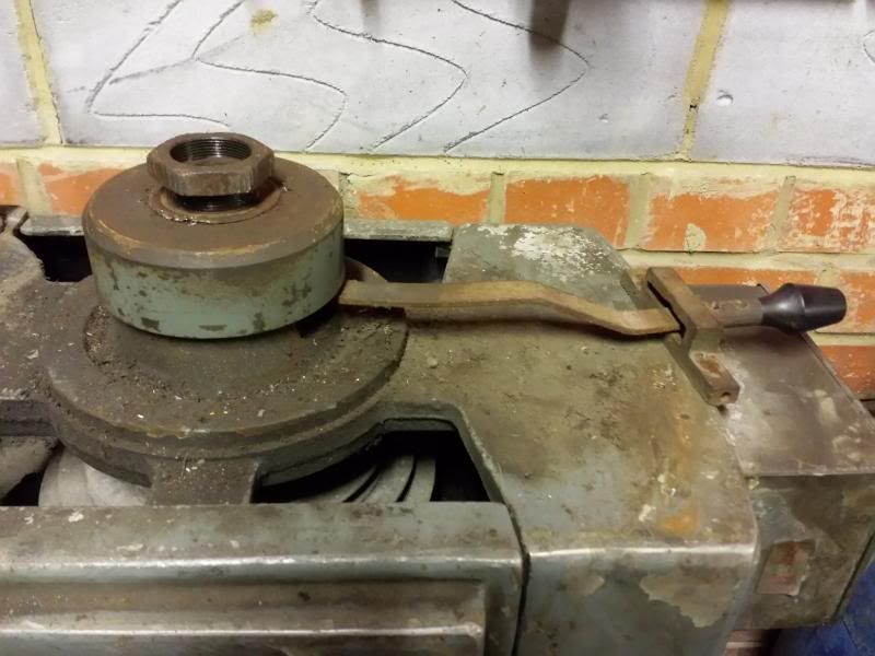
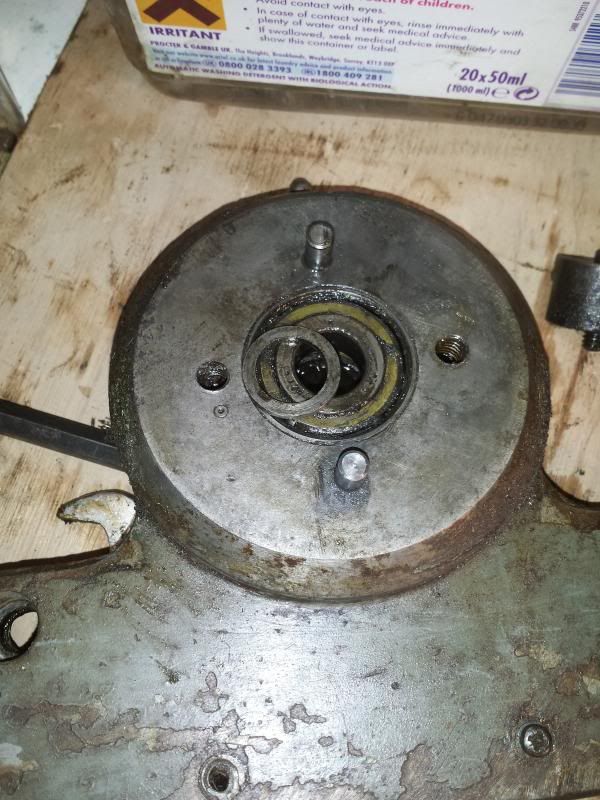
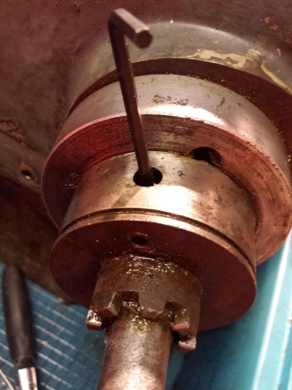
The head also has a lever operated braking system that sits on top of the main spindle.
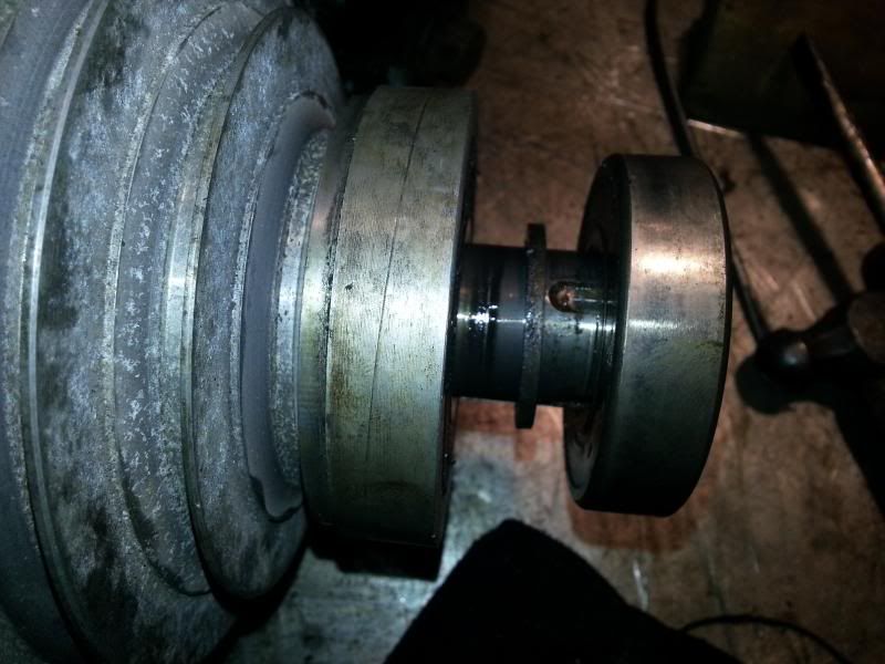
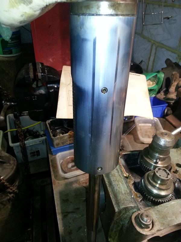
Undo the locking washer and nut on top and the brake "drum" together with expanding shoes pops off the top of the spindle. The pulley cover can then be removered after undoing about 6 hex head bolts. In the picture below the top part is where the brake mechanism sits then there is a bearing beneath.
Underneath this is the second pulley wheel which is connected to the main drive shaft via a toothed belt. At this stage I tried to remove the brake attachment from the top of the spindle but couldn't see how it was attached. It does have a couple of grub screws as seen in this photo
but even with these backed of I couldn't budge it. It looked like it was threaded on but turning the top just wound the quill in and out so I left it in situ for the moment. Having got the motor off I decided it would be easier to work on the head on the bench, so 4 large bolts on the front face of the head were removed and the the head will seperate from the arm. In this pic you can see the screw/gear arrangement that allows you to cant the head from side to side (it will swivel 180 deg on these almost making it into a horizontal miller)
Cheers, Paul.
Edited By Paul Major on 26/01/2014 14:05:35 |
| 26/01/2014 13:48:03 |
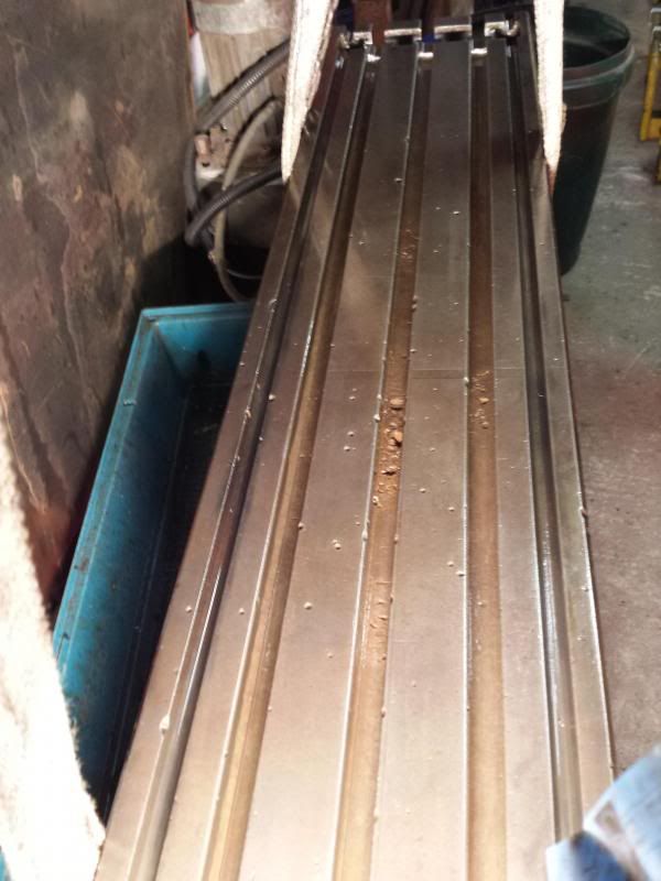
Not been able to do any updates for a while, broadband has been down. Took BT a week and 3 different engineers visiting to get it working again Anyway got to work on the table. Tried various approaches ended up going over it with a brass wire brush after lots of attacks with degreaser. Not sure it will ever end up looking like one of those nice new polished chrome looking mills but at least its clean
Cheers, Paul. Edited By Paul Major on 26/01/2014 13:49:06 |
| 10/01/2014 00:05:50 |
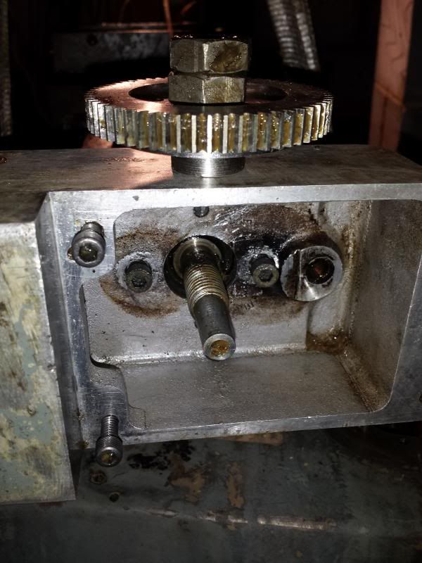
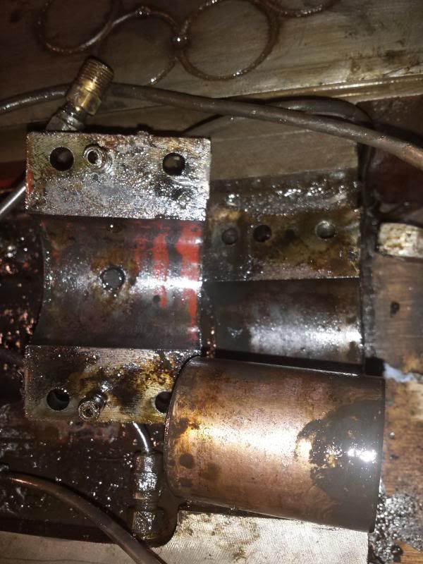
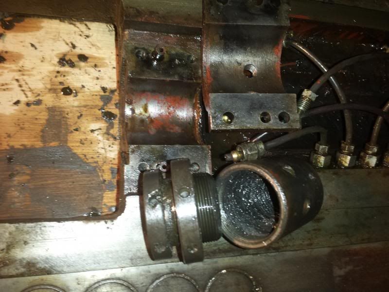
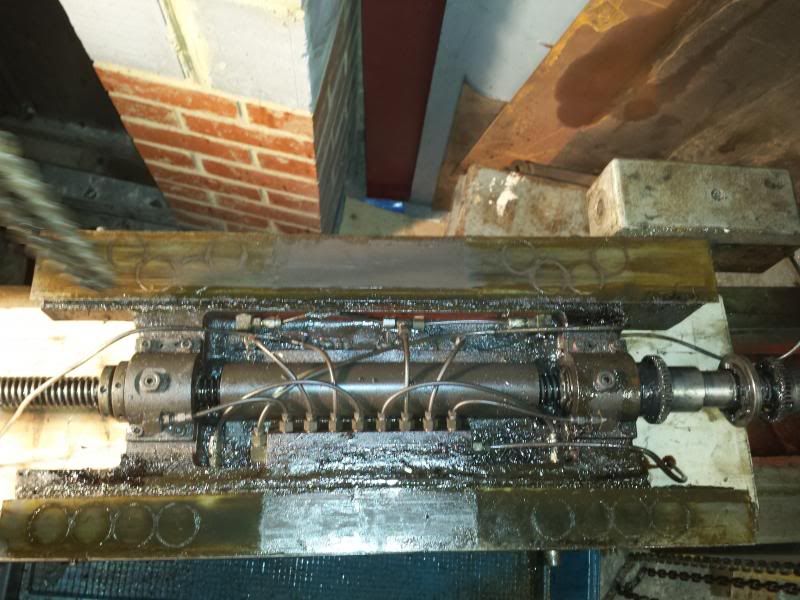
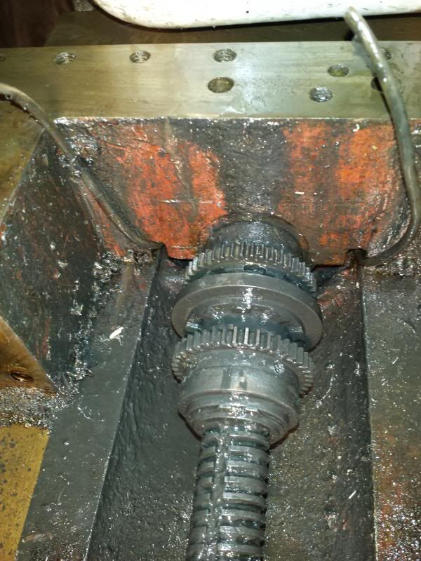
The leadscrew has two motors, a rapid return and a slow feed. Again the manuals only show hand screws for the table feed but I know the rapid return was an option on these mills – just don’t know which end is which So removed the gearbox cover plate and waded through masses of greases to find a cog held on by a double nut.
Removing this allows you to remove two bolts that hold the gearbox to the table end bracket. This houses the bearing the end of the leadscrew runs in and is located on 2 dowels.
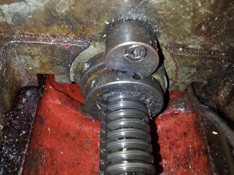
The table feed gearbox assembly is held in place on the leadscrew with a circlip and thrust washer.
Having loosened the gears at one side of the saddle and backed of the backlash adjustment collar on the other side I then gradually removed the oiler reservoir and tubing.
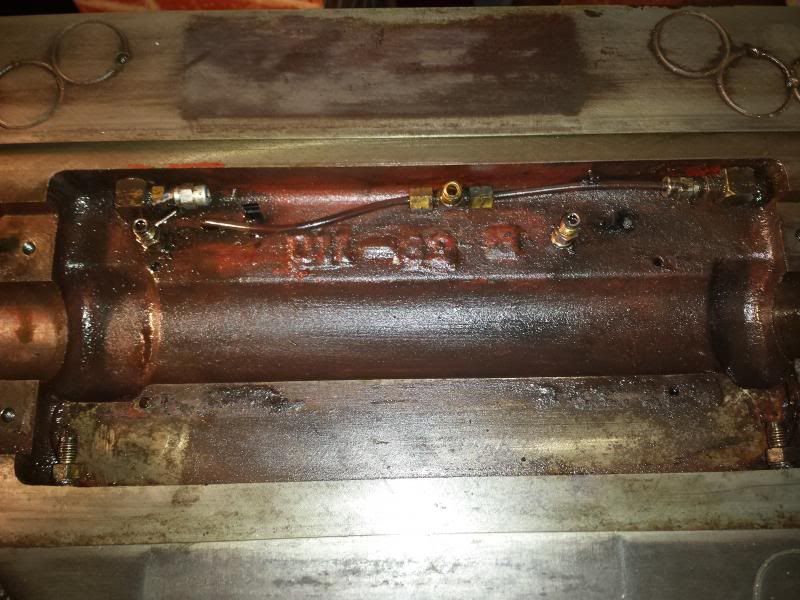
The leadscrew sits in 2 bushes held in place by bearing caps
With the caps, tubing, and shield removed the leadscrew will then lift off the table.
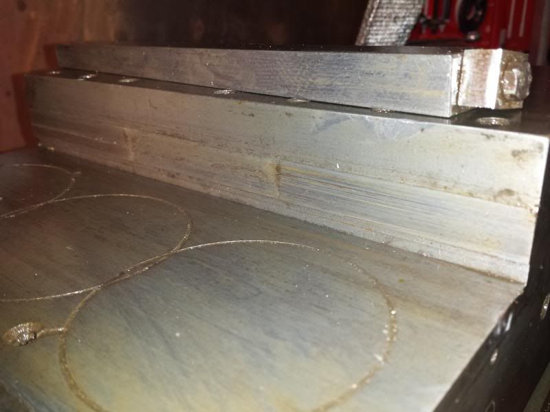
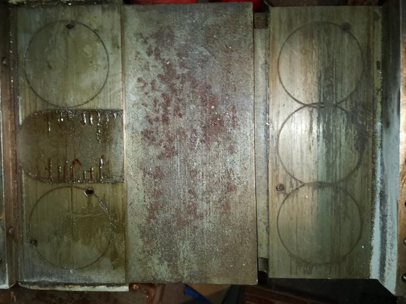
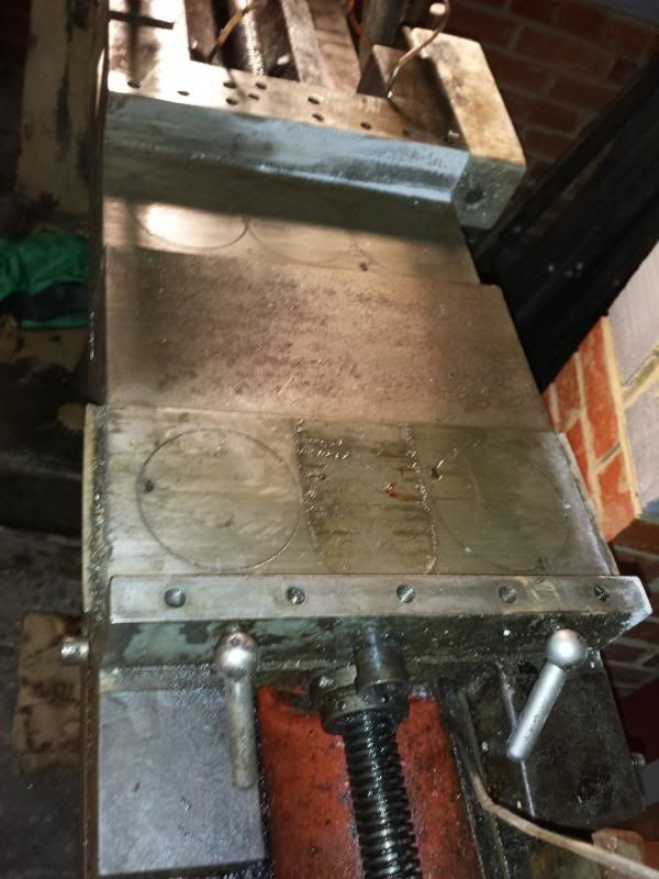
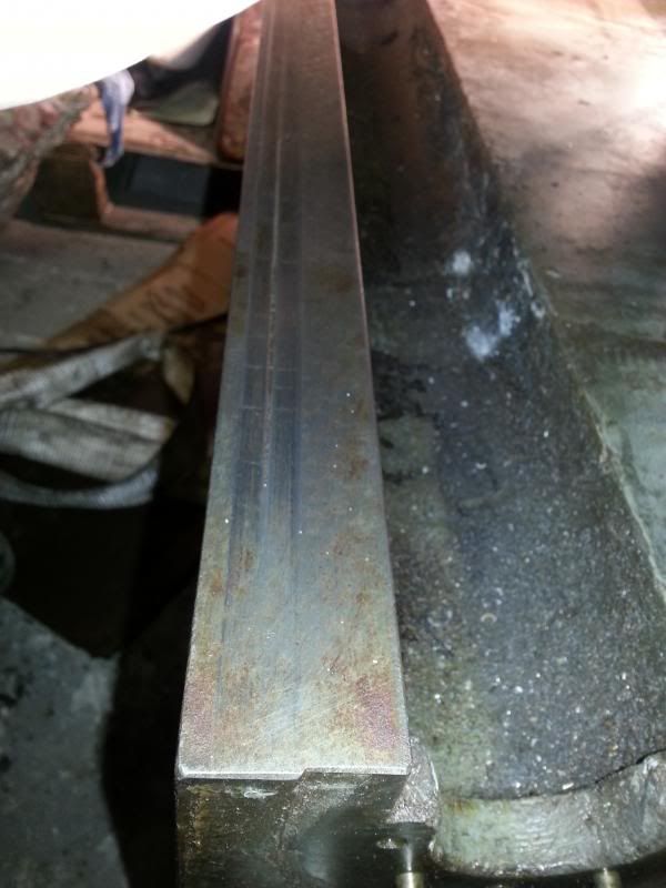
Having cleaned up the saddle some more I gave it a closer inspection. These are the ways that match up to the outside of the saddle. They seem to have matching grooves worn in them.
I wonder if at some point swarf has become lodged in-between these two surfaces and scored the surface. As mentioned above when discussing the knee, my challenge will be deciding whether it is worth trying to reface these surfaces, or whether to refit the saddle to the knee and once adjusted with the gib, ascertain if it causes any real tolerance issues. The saddle to knee gib looks in reasonably good condition.
So that’s it, saddle and table stripped, now onto some more cleaning Cheers, Paul. |
| 09/01/2014 23:32:15 |
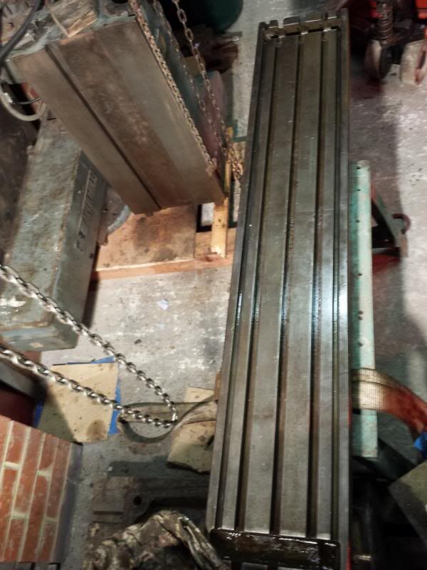
With the knee stripped and cleaned it was time to move on to the table. A bit more playing with block and tackles and we have the table mounted ready for work .
The table is upside down obviously (and weighs a ton!) but this allows me to check out the ways/mating surfaces on the saddle to knee area.
The last pic shows the two locking pins that lock out the saddle to knee. Next step I thought was to remove the leadscrew but I couldn’t see any way of doing this with the saddle in place, so the saddle came off. I guess if it was all assembled this would be the same procedure for removing the table. The saddle is held in place with two tapered gibs adjusted by a double nut arrangement (forgot to take pictures). With the gibs removed the saddle can be lifted off the table ways to reveal a spaghetti junction of oil pipes where someone had fitted an auto oiler!
One side of the saddle is what the manual refers to as a “table feed gearbox assembly”. To be honest I haven’t got my head around how this works as the table and saddle where already removed when I picked up the mill.
The other side of the table is the backlash adjustment screw together with a retaining collar.
So that’s the saddle off, next job, remove the leadscrew. Cheers, Paul. |
| 09/01/2014 17:45:57 |
Thanks Russell, all safely downloaded It is slightly different to mine so that's great, all knowledge is good knowledge Back to cleaning duties now - what a pain cleaning 300kg lumps of metal is!! Cheers, Paul. |
| 06/01/2014 17:09:10 |
I know what you mean on the Googling In that diagram it references the Knee feed gearbox assembly diagram, don't suppose you have that do you? Does it cover anything on the setting up of gibs etc? I guess easiest answer is a copy of the contents page then I can compare it to mine Cheers, Paul.
|
| 06/01/2014 15:56:39 |
Posted by Russell Bates on 06/01/2014 10:47:17:
Paul, Let me know if you need a copy.
Hi Russ Thanks for the offer. The handbook I have is titled "Instruction Manual Beaver VBRP Mk2 Turret Miller" and is 50 pages. Has some parts diag's and info on belts etc but not terribly detailed. Is that the same as yours? Thanks, Paul. Edited By Paul Major on 06/01/2014 15:57:02 |
| Thread: Acceptable wear limits on a milling machine |
| 05/01/2014 16:37:00 |
Thanks guys, off to read up on tramming Also need to understand better how much wear you can take out with adjusting the gibs. The way on the edge of the knee where the saddle gibs clamp onto has a slight groove worn in it about 5 thou deep, need to figure out how much this will affect things.
cheers, Paul. |
| 05/01/2014 11:49:36 |
Thanks Dave, been reading up on scraping, may end up having to do some but was trying to figure out which bits would need it most as I don't really want to spend days scraping every surface Any advice on how to measure wear on the different surfaces? Cheers, Paul. |
| Thread: Restoring Beaver VBRP Mill |
| 05/01/2014 11:46:38 |
Posted by John Stevenson on 31/12/2013 20:34:35:
having said that do you have 5" on this model or 6" ? Hi John, not sure if the quill is 5" or 6" yet, head and arm will probably be the last bit I refurb. Thanks for the encouragement Michael, makes a difference when you spend hours writing this stuff up Hopefully helps someone else out as well and gets me a bit of good advice along the way. Cheers, Paul. |
| 05/01/2014 00:16:55 |
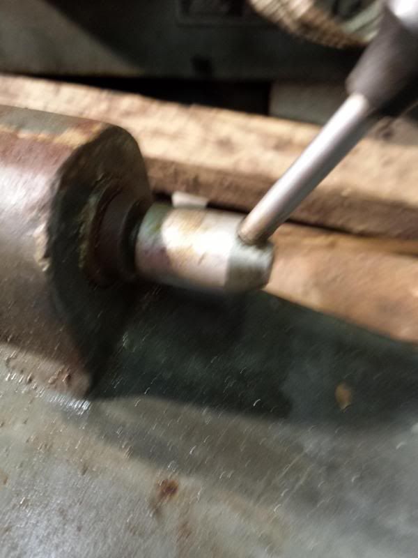
Pretty miserable weather outside and still too windy to go up and replace the tiles lost from the roof over the last week soooo, More time in the workshop Continued with the cleaning of the knee. First job was to remove the handle and mic ring etc from the knee feed screw. After the huge effort it took to get the saddle feed handle and leadscrew out I have to say i wasn't looking forward to it! In the end it took about 5 mins
The collet the ring sits on had the same set up as the saddle, one obvious grub screw, a tapered pin and one less obvious grub screw under the ball bearing on the mic ring lock.
After removing these the collet ring itself came off really easily and then the Hoffman bearing and the 2 machine screws holding the spacer ring onto the knee could be taken off.
I had already unscrewed the knee pillar from the riser screw so now the complete leadscrew/gears/riser came out as one unit after removing a couple of machine screws that held it to the knee.
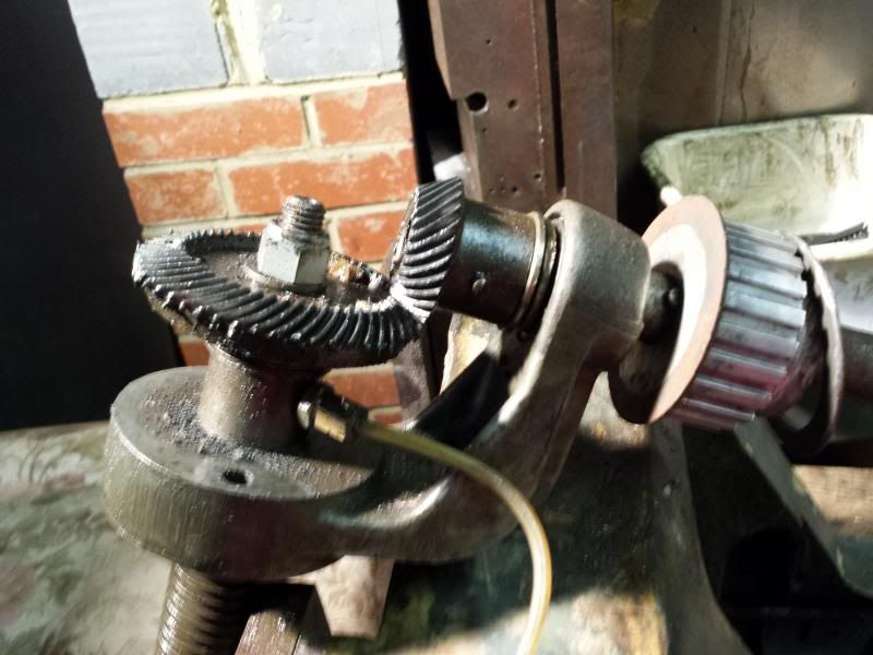
The motor for the knee is a later addition. The bevel gear on the end of the leadscrew is held on with a tapered pin, once this is removed the leadscrew pulls out of the carrier. Next job was to remove the knee retaining plates and gibs. Started by removing the handle from the knee lock.
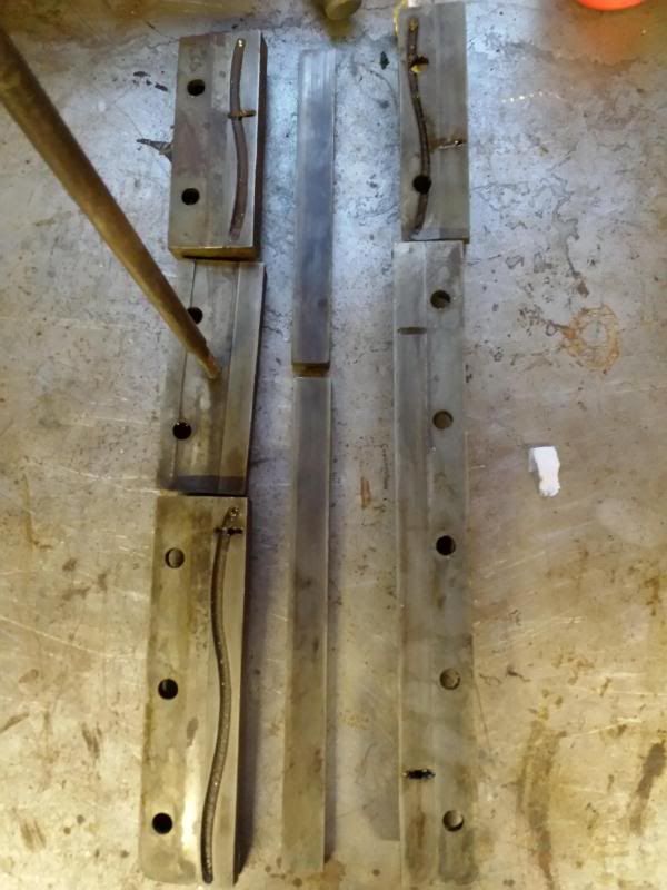
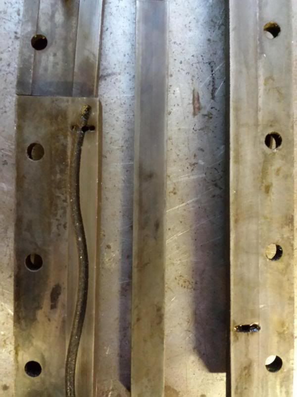
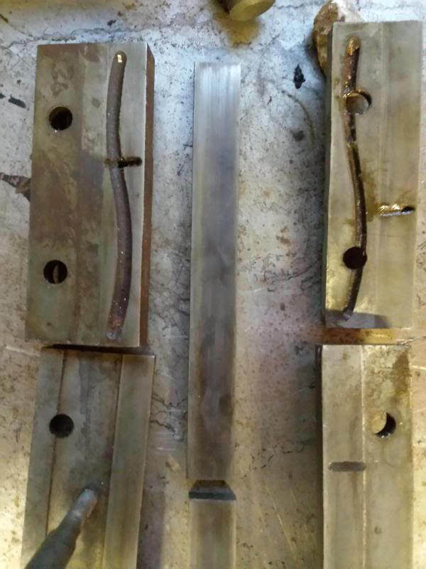
The shaft this operates on is attached to one of the retaining plates as you will see in a minute. Said retaining plates were removed along with the gibs. These are straight gibs on the knee adjusted by a series of grub screws. Some pics of the plates and gibs.
I don't know if the grease points or channels were a later addition but it seems odd that 4 plates have "s" shaped channels and 1 doesnt, and on 3 of the plates the grease point is drilled into the channel and on 1 it isnt! Plates and gibs look kinda OK, but not got any real experience to go on here about how to check/measure. What was noticeable was the adjustment on the gibs seemed odd. The top grub screw (in the picture) was snapped off and the middle and bottom ones both had been wound in about 2-3mm whereas the ones in between were flush. This implies to me the gibs on the knee hadn't been properly adjusted, but I'm no expert!.
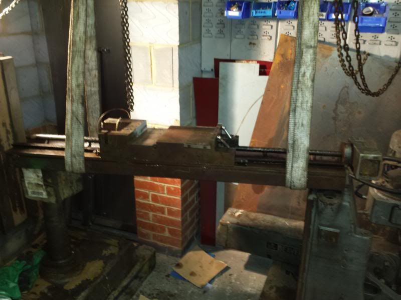
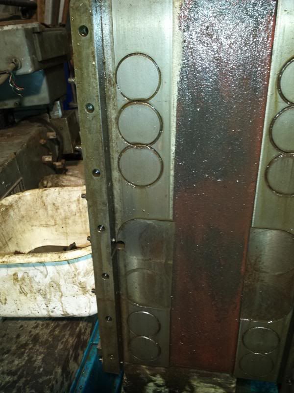
I could then give the whole knee a wash down to get all the oil/grease/rubbish off and set it to one side ready for refurbing. I am soooooo enjoying having my new beam, trolley clamp and chain block, it is making this project so much easier Just out of interest, as part of the refurb I was planning on stripping and painting the mill. This pic gives you an idea of how much filler/effort they put into prepping the mill for paint when it was first produced.
Cheers, Paul. Edited By Paul Major on 05/01/2014 00:23:02 |
| Thread: Acceptable wear limits on a milling machine |
| 04/01/2014 23:01:38 |
Hiya, got a thread running over in the manual machine tools section detailing the rebuild of my Beaver mill. As I am stripping it down I am noting some wear on the ways for the knee, saddle and table. Its a big old beast and I didn't have the chance to see it working before I got it so can't tell how much movement there was on the different axis. So, in general, what sort of wear can you get away with on the relevant surfaces? Whats the best way to measure the wear and what would you do to fix it? Any advice gratefully received Thanks, Paul. |
| Thread: Restoring Beaver VBRP Mill |
| 03/01/2014 21:26:25 |
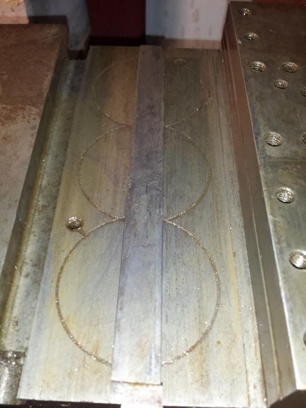
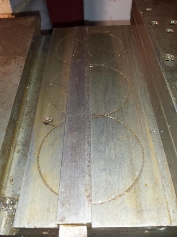
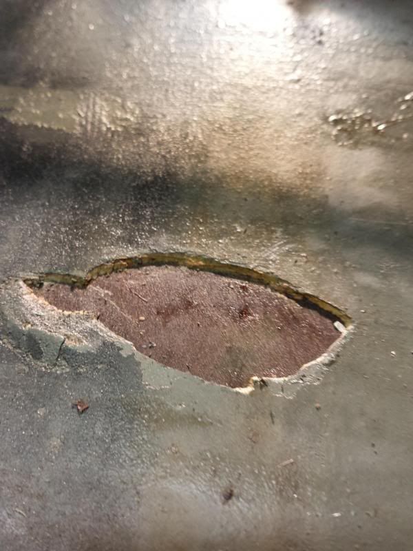
The top surface of the knee looks to be in pretty good condition as well. At a guess it looks like the gib has been too tight and has worn a grove at this end.
The opposite side is fine but there is a definite groove worn here. Not sure how much impact this will have on the accuracy of the mill. Have run a DTI across it and it is about 5 thou deep, peaking at 10 thou where the line is in the middle of the groove. So, the big question is, what sort of tolerances/wear should I deem acceptable on a mill like this. When built it will be used for mainly engine work, skimming heads, fly cutting etc. I didn’t get a chance to see it up and running when I bought it so don’t really have a good idea of how tight it was. With the knee in place it is way too heavy to feel any movement in the knee and I haven’t reassembled the saddle to check this. Have seen threads on scraping etc but was hoping to avoid this if possible. So, what’s the collective wisdom here, what should I accept on the mating faces and how should I go about improving them? Cheers, Paul. |


![[IMG]](http://s1117.photobucket.com/user/mm289/media/Workshop/2013-12-27185025_zpsc7dc668b.jpg.html)
![[IMG]](http://s1117.photobucket.com/user/mm289/media/Workshop/2013-12-27184929_zpsfb60c690.jpg.html)
![[IMG]](http://s1117.photobucket.com/user/mm289/media/Workshop/2013-12-27184939_zps0794b057.jpg.html)
Magazine Locator
Want the latest issue of Model Engineer or Model Engineers' Workshop? Use our magazine locator links to find your nearest stockist!
Sign up to our Newsletter
Sign up to our newsletter and get a free digital issue.
You can unsubscribe at anytime. View our privacy policy at www.mortons.co.uk/privacy
Latest Forum Posts
- *Oct 2023: FORUM MIGRATION TIMELINE*
05/10/2023 07:57:11 - Making ER11 collet chuck
05/10/2023 07:56:24 - What did you do today? 2023
05/10/2023 07:25:01 - Orrery
05/10/2023 06:00:41 - Wera hand-tools
05/10/2023 05:47:07 - New member
05/10/2023 04:40:11 - Problems with external pot on at1 vfd
05/10/2023 00:06:32 - Drain plug
04/10/2023 23:36:17 - digi phase converter for 10 machines.....
04/10/2023 23:13:48 - Winter Storage Of Locomotives
04/10/2023 21:02:11 - More Latest Posts...
- View All Topics
Support Our Partners


Shopping Partners
Subscription Offer

Latest "For Sale" Ads
- Reeves** - Rebuilt Royal Scot by Martin Evans
by John Broughton
£300.00 - BRITANNIA 5" GAUGE James Perrier
by Jon Seabright 1
£2,500.00 - Drill Grinder - for restoration
by Nigel Graham 2
£0.00 - WARCO WM18 MILLING MACHINE
by Alex Chudley
£1,200.00 - MYFORD SUPER 7 LATHE
by Alex Chudley
£2,000.00 - More "For Sale" Ads...
Latest "Wanted" Ads
- D1-3 backplate
by Michael Horley
Price Not Specified - fixed steady for a Colchester bantam mark1 800
by George Jervis
Price Not Specified - lbsc pansy
by JACK SIDEBOTHAM
Price Not Specified - Pratt Burnerd multifit chuck key.
by Tim Riome
Price Not Specified - BANDSAW BLADE WELDER
by HUGH
Price Not Specified - More "Wanted" Ads...
Get In Touch!
Do you want to contact the Model Engineer and Model Engineers' Workshop team?
You can contact us by phone, mail or email about the magazines including becoming a contributor, submitting reader's letters or making queries about articles. You can also get in touch about this website, advertising or other general issues.
Click THIS LINK for full contact details.
For subscription issues please see THIS LINK.
Digital Back Issues


Donate

 Register
 Log-in
Model Engineer Magazine
- Percival Marshall
- M.E. History
- LittleLEC
- M.E. Clock

ME Workshop
- An Adcock
- & Shipley
- Horizontal
- Mill

Subscribe Now
- Great savings
- Delivered to your door

Pre-order your copy!
- Delivered to your doorstep!
- Free UK delivery!